details
Introduction
WizFi shield uses Wiz820io, WizFi210 module and supports the Ethernet and Wi-Fi connectivity simultaneously.
1. Hardware
a) Ethernet
-. Wiz820io is connected with SPI signals.
-. Other signals
- /SS_WIZ (Input): SPI slave chip select signal
- /RESET_WIZ (Input): H/W reset signal
- PWDN (Input): Set power down mode
- /INT_WIZ (Output): Interrupt signal

b) Wi-Fi
-. WizFi210 module is connected with SPI signals
-. Other signals
- /SS_WIFI(Input): SPI slave chip select signal
- FAC_RST (Input): Factory reset
- GPIO19 (Output): If this signal is high, indicate the data in the receive buffer in the WizFi210
- WIFI_RST (Input): Reset signal

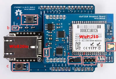
c) Hardware description

- a: WizFi210 Factory Reset button
- b: Power LED
- c: Reset button
- d: Power LED of WizFi210
- e: Pin header: Select RUN mode or F/W update mode of WizFi210
- f: Pin header: UART Interface of WizFi210
- g: LEDs: Indicate the operation of WizFi210
- h: Antenna
2. How to test?
a) Test environments

. WizFi Shield gets the IP address using DHCP and works as TCP server.
-. Laptop connects to it. After the connection is established, the data between the laptop and WizFi shield is transparent.

- Arduino source code & schematics can be download from Wiznet Github https://github.com/Wiznet/Arduino_WiFi_Shield
- WizFi210 datasheet: http://www.wiznet.co.kr/UpLoad_Files/ReferenceFiles/WizFi210-User_Manual_EN_V1.11.pdf
- Wiz820io datasheet : http://www.wiznet.co.kr/UpLoad_Files/ReferenceFiles/iEthernet_W5200_datasheet_v1.2.7_en.pdf
COMMENTS