BoosterPack
BoosterPack plug-in modules can really help your LaunchPad-based projects soar. These innovative tools plug in to the header pins on the LaunchPad and allow to you to explore different applications that your favorite TI MCU can enable. There is a broad range of application-specific BoosterPacks available from both Texas Instruments and third parties, including capacitive touch, wireless sensing, LED lighting control and much, much more. BoosterPacks are available in 20- and 40-pin variants and multiple BoosterPacks can plug into a single LaunchPad to greatly enhance the functionality of your design.

EthernetBoosterPack
Developed by 43oh.com(TI MSP430 community) and here are some specs so far:
- WIZnet’s W5200 Ethernet controller chip (W5100 or W5300 is an option.)
- MagJack
- LDO + power header
- Opto isolators (2 or more) + output header
- Input/output header for switches/keypad/display
- DIP or SMD MSP430G
W5200 was used because…
W5200 chip is a Hardwired TCP/IP embedded Ethernet controller that enables easier internet connection for embedded systems using SPI (Serial Peripheral Interface). The W5200 is composed of a fully hardwired market-proven TCP/IP stack and an integrated Ethernet MAC & PHY. Hardwired TCP/IP stack supports TCP, UDP, IPv4, ICMP,ARP, IGMP, and PPPoE. By using W5200, users can implement the Ethernet application they need by using a simple socketprogram instead of handling a complex Ethernet Controller.In other words, you do not have to deal with or waste resources on TCP/IP stack.
Webserver
The whole thing takes up just under 4.5KB and uses ~400 bytes of RAM, so you still have ~11KB and ~100 bytes of RAM left for whatever you need.
Server software allows reading and writing MSP430’s registers. There are port masks that will prevent changing setting of pins used for controlling W5200, so don’t worry, you can set port registers as you please. Response can be in HTML or XML format.
#define RESPONSE_TYPE_HTML // comment out to switch to XML
Here are commands:
http://x.x.x.x/g?t=p get all ports
http://x.x.x.x/g?t=p&n=2 get port 2
http://x.x.x.x/s?t=p&n=1&v=0xFF set P1OUT to 0xFF
http://x.x.x.x/s?t=d&n=2&v=2 set P1DIR to 2
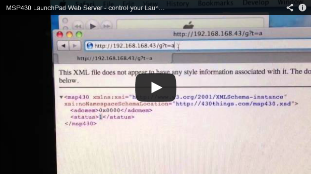
http://x.x.x.x/g?t=a get ADCMEM (0x0000 is returned when ADC is disabled)
http://x.x.x.x/g?t=m&n=2&v=100 get memory dump, 100 byte starting at address 2 * 256
You should set n & v when reading memory, or you will dump the entire address space 64k, which will most likely lock up the server. I will fix that later on.
Want to know you calibration data? Well, it’s at 0x1000
http://x.x.x.x/g?t=m&n=0x10&v=0xFF
Possible port targets:
t=p PxIN // for reading only
t=o PxOUT
t=d PxDIR
t=r PxREN
t=s PxSEL
t=t PxSEL2
t=i PxIE
t=e PxIES
t=f PxIFG
n = port number n=1 P1, n=2 P2, etc. (used with port registers)
n = start address (high byte) n=4 means start at 4 * 256 = 1024, or n=0x10 start address is 0x1000 (used with t=m)
v is the value in hex or decimal, from 0-255 or 0x00 to 0xFF, case insensitive (used with port registers)
v is the number of bytes to return v=100 means return 100 bytes, or v=0x0F return 16 bytes (used with t=m)
Source Code & How to use
Ethernet Booster Pack available at 43oh store. and the source code can be downloadable here.
- download attached zip file and paste all files into your project
- change IP addresses in main.c, local and gateway, and subnet mask if needed.
- compile and run, that’s it.
If you want to use this software with any other Ethernet boards, just change one line in the defines.h
#define W5200_BOOSTER // booster
//#define W5200_SERVER // stand-alone version
//#define WIZ820_BOOSTER // WIZ820io booster pack
//#define WIZ820_SERVER_G // WIZ820io server board, G series
Default ports:
MOSI – P1.7
MISO – P1.6
SCLK – P1.5
SS – P1.0 (W5200 select)
W5200 INT pin is not connected. JP1 jumper will connect INT to P1.3, JP2 to P2.7
W5200 PWDN is grounded (JP4,) JP3 will connect P2.0 to PWDN
W5200 RST is connected to P1.4 (JP5,) JP6 will let you use P2.6
If you want to run it as a stand-alone, solder the chip, C20 (0.1uF,) R23 (47k,) and C19 (1nF.)
To use LDO, solder IC1 (any SOT223 LDO with Vout in the middle,) C5, and C18 (~10uF.)
OK1 is a single dual channel or two single channel opto couplers, R24 & R25 are opto’s current limiting resistors.
Plug in Ethernet cable first, then power up LP/booster pack.
Some routers may not be happy with constant changes, unplug all, wait few seconds, plug everything back in.
For more information, refer to this.
COMMENTS