HTML 5 is the most enormous leap for the web standard protocol in the past decade. Maybe you already realized how convenience for HTML 5. For help you to expand the application based on this platform. This article wills analysis the perfect combination of “Smart Home” and HTML 5 deeply and let Home network real-time monitoring can be easier implemented.
Smart Home
In 2013, many companies already have the idea for Smart Home application, such as SAMSUMG, Philips, etc. In CES exhibition, SAMSUNG showed their New Intelligent Cleaning Robot and Philips showed Hue Smart LED light bulb. Also Nest’s Smart thermostats and smart home which combined smart control, smart terminal and smart display.
All of those products let us think that smart home is not only concept now, but already entered to commoditization stage. Convenient, security, economical, and practical still the most concerned points from users. So remote monitoring is get more popular undoubtedly, especially when your home have elderly, children, or your pets, if any emergency situation is happen, how can you know this circumstances to avoid an accident in the first time?

Picture 1 Home monitoring system block diagram
Based on this block diagram, it is possible to DIY your own home network real-time monitoring by your smart phone or PC which connect to the Internet. Then you can monitor the status of all corners in your home through Internet. So we would like to introduce how to use one MCU board with Ethernet and one webcam to monitor your home in real time by adopt HTML 5 platform.
HTML5—WebSocket data transfer
Real time network access, Can the quality of the image achieve the desired value?
Previous, it is use polling for data acquisition and display in Web interface. The timeliness of data is not good. If the data polling is too fast, not only increase the burden on the browser, but also may not reach the desired effect. The reason of adopt HTML 5 is that it add the websocket API function as almost the perfect solution for solving the real time issue.
We are using MCU for upload the collected data to the webpage. But there have the limitation of size for loading the data in the buffer. So we direct output the collected image data as JPEG platform for solving this problem. Just set the playback rate as 5 frames per second temporarily. That means each second switching 5 frames. Then we can watch the video in the webpage.
WebCAM system demonstration
- System environment:
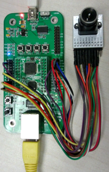
a) MCU:STM32F103RC,256K Flash,48K SRAM,2K EEPROM
b) Ethernet controller:W5500,Connect to MCU by SPI interface
c) Power supply:USB
d) Webcam:OV2640

Picture 2 W5500EVB and OV2640 Webcam
- Development tools: IAR for ARM v5.41which is the version we are using now. If you use different version IAR, please adjust the STM library.
- Before looking at the code, let’s go through the whole program flow. The flow chart consists of a main flow chart and two sub-flowcharts. As shown below, the program using polling mechanism to process the request and image data.After the initialization is complete, then it will configure the W5500 network parameters (ex. IP address) which should be based on your own network situation for ensure the W5500 can connect to Internet. In this program, we will create two sockets in W5500. One is for create a HTTP Server. When you input the configured IP address in the web browser, web browser will remote access the hardware as Client mode. Another one is for create a Web Socket Server for transmit the webcam image date as communication link with webpage.

Picture 3 System main flow chart

Picture 4a Http process function flow chart

Picture 4b WebSocket process function flow chart
When user access the hardware’s IP address in the web browser, it will send http request to W5500. After W5500 received the request, it will send the HTML 5 webpage program to web browser. In the webpage program, web browser will set up the WebSocket connection with hardware actively. After completed the handshake operation, image data transmission channel will be established. Whenever hardware is polling a new image is ready, it will be sent the image data to the browser via WebSocket, the browser receives the data, draw the image on the screen.The actual effect diagram please see Figure 5. Next, we will introduce the detail of the initialization of the webcam and the procedure of HTML 5 draw the image on the canvas and the procedure of WebSocket data transfer in the image data buffer program.

Picture 5 Actual effect diagram of web browser

Picture 6 Actual operation situation
OV2640 Introduction
- OV2640 hardware introduction

Picture 7 OV2640 Webcame
The maximum output pixel of OV2640 is 200M pixels, support QCIF(176*144), QVGA(320*240), VGA(640*480), 1027*768 and 1600*1200 pixel output.
Provide two kind of output formats:
a、The original data, such as RGB565,RGB RAW,YUV422;
b、JPEG compressed image format(can greatly reduce the transmission bandwidth, such as 640 * 480 resolution of the original image size is about 300KB, the size of the JPEG encoder output is only about 16KB)
In this system, since we usethe original data format, the image file is too large (In example of RGB RAW, one frame image file size is 640 * 480 * 3 = 900Kbytes). It affected the data transfer speed and the frequency of the image update, thereby affecting the actual effect of browser video display;Also the processing capacity of STM32F103RBT6 is limited, it can’t do the complex image compression algorithm, so choose the compressed JPEG image format is the best choice which compressed by OV2640 internal DSP.
The communication between MCU and OV2640 is combined with serial and parallel, OV2640 with SCCB (Serial Camera Control Bus) two-wire serial interface, MCU configured via the SCCB interface and read OV2640 information; MCU receive OV2640’s image datavia use parallel bus. Hardware connection diagram of the system as following:

Picture 8 Hardware connection diagram
Among them, Y (2..9) as 8 bit MSB (Most Significant Bit mode) parallel bus. SDIO and SCLK as SCCB interface. PCLK as pixel clock output pin (output from a parallel bus pixels per each cycle). VSYNC as column sync output pin (occurs once every frame transitions). HERF as line reference output pin (the parallel bus output one line of image data per each cycle).The timing reference of SVGA mode as following:

Picture 9 the output image timing diagram in OV2640 SVGA mode
After power on the system, MCU configure the operation mode of OV2640. After OV2640 prepare the image, VSYNC will be pulled for some time, MCU receive the image data in bytes through interrupted by the rising edge of PCLK. Next we will introduce the OV2640 initialization configuration program and image data buffering procedures.
2. OV2640 program introduction
Initialization configuration program:
iic_init();/*Initialize MCU,I2C_2 and OV2640 SCCB communication interface*/
ov2640_jpeg_config(JPEG_640x480); /*Configure the output image format */
/* Configure COMS parameters */
ov2640_brightness_config(0x40); /*Configure brightness mode: +2*/
ov2640_auto_exposure(3); /*Configure auto exposure level 0-4*/
ov2640_contrast_config(0x28,0x0c); /* Configure contrast:+2*/
ov2640_black_white_config(0x00); /*Configure Black & White mode: normal mode */
ov2640_color_saturation(0x68,0x68); /*Configure color saturation: +2*/
ov2640_light_mode_config(OFFICE); /*Configure scene mode: Office */
o2640_capture_gpio_init();/*Initialize parallel transmission IO pin */
PS: Above source located in “main.c”
Image data buffering program:
u8 temp;
EXTI_ClearITPendingBit(EXTI_Line0);/* Clear PC0(PCLK)interrupt*/
if(GPIO_ReadInputDataBit(GPIOC,GPIO_Pin_1)==0)/*HREF pin as low*/
return;
temp =(u8)((GPIOC->IDR)>>8&0x00ff);/*read 1 byte image data */
switch(jpg_flag)
{
case0:
if(temp==0xff)/*Image data use 0xff 0xd8 as header*/
{
JPEGBuffer[4]=0xff;
jpg_flag=1;
}
break;
case1:
if(temp==0xd8)
{
JPEGBuffer[5]=0xd8;
jpg_flag=2;
JPEGCnt=6;
}
elseif(temp!=0xff)
jpg_flag=0;
break;
case2:
JPEGBuffer[JPEGCnt++]= temp;/* Save the data */
if(temp==0xff)
jpg_flag=3;
break;
case3:
JPEGBuffer[JPEGCnt++]= temp;/* Image data use 0xff 0xd9 as end*/
if(temp==0xd9)
{
jpg_flag=4;
counter++;
}
elseif(temp!=0xff)
jpg_flag=2;
break;
case4:
break;
}
PS: Above source located in “websocket.c”
In the interrupt function, it can read each image data frame correctly through above cache data. JPEGBuffer as a global image cache, the WebSocket data transmission function can detects the buffer zone data is ready, then it will send the image to the browser.
Draw the picture in Canvas
The interesting aspect of Canvas API is image support. We can have variety of methods for operating image through using drawImage function. There have three formats in drawImage:
- drawImage(image, dx, dy):Displayed the specified image URL dx, dy position
- drawImage(image, dx, dy, dw, dh):Scaled the displayed image according tothe width (dw) and the display height (dh)
- drawImage(image, sx, sy, sw, sh, dx, dy, dw, dh):Cut a portion of the image for display according to X, Y coordinates , the width and height (sx, sy, sw, sh)
The following is the webpage program about how to achieve the image drawing:
- Firstly, create a canvas
<p><canvasclass=‘img filter-drop-shadow’id=‘cam’alt=‘W5500照相机‘></canvas></p>
- Defined the canvas margins, width , height, etc.
.img{margin:0 auto;display:block;margin-bottom:10px; width:640px;height:480px;cursor:pointer;}
3. In order to draw image to canvas in JavaScript, it needs to get the drawing environment through the target canvas’s id firstly. Code needs to get the canvas’s element through the canvas’s id, and then use this element’s getContext method to get itstwo-dimensional drawing environment for reference.
var canvas =document.getElementById(‘cam’);
var context =canvas.getContext(‘2d’);
4.WebSocket received the data and draw the image
websocket.onmessage= function (evt)/*Received the message from Server and use evt.data to extract*/
{
var image = new Image();
image.onload= function ()
{
context.clearRect(0,0,canvas.width,canvas.height);/*Clear canvas rectangular area */
context.drawImage(image,0,0,canvas.width,canvas.height);/* Draw the image with width as 640px and Height as 480px*/
}
image.src=URL.createObjectURL(evt.data);/* Generate the imageURL information */
}
This shows that we used the second drawImage format, specify scaled size so that it matches the size of the canvasexactly, and the image we get from the OV2640 is the same size as the canvas.
PS: Above source located in “webpage.c”
WebSocketData transfer program
Here will introduce the program for how to handle large data transfer.
if(handshaked)/*Handshaked success */
{
uint32jpgLen=0;
uint32 send_len=0;
uint8firstByte=0x82;//FIN=1, opcode=0x02: binary
uint8secondByte=126;//no mask, extend length=2 bytes
uint8 extend[2]={0x00};//extend header
while(jpg_flag!=4);/*Image buffer is completed */
jpgLen=JPEGCnt;
extend[0]=(jpgLen–4)/256;/*Extract payload High 8 bit*/
extend[1]=(jpgLen–4)%256;/*Extract payload Low 8 bit*/
/*Packagingwebsocket data packet*/
JPEGBuffer[0]=firstByte;
JPEGBuffer[1]=secondByte;
JPEGBuffer[2]=extend[0];
JPEGBuffer[3]=extend[1];
while(jpgLen)
{
if(jpgLen>WS_PACKET_LEN)/* if LAN higher W5500 transmit buffer size(4K default)*/
{
send(s,(uint8*)(JPEGBuffer+send_len), WS_PACKET_LEN);
send_len+= WS_PACKET_LEN;
jpgLen-= WS_PACKET_LEN;
}
else/*Send the remaining packet */
{
send(s,(uint8*)(JPEGBuffer+send_len),jpgLen);
send_len+=jpgLen;
jpgLen-=jpgLen;
}
}
if(jpg_flag==4)/*After the transmission is completed, reset the image capture flag */
jpg_flag=0;
printf(“.%d\r\n”,send_len);/*Print the data packet length for debug */
}
As the small packet length is only 7 bytes, it will not use the extend byte. After compressed the collected image from OV2640 and one frame image data is much larger than 125 bytes, it need to use the extend byte for characterize the data length. After test, one frame image data is around 12Kbytes when OV2640 in the JPEG_480*640 mode. So just need to use two extend byte(16 bit, represent 65,535 bytes(maximum)) . According to the definition format of data packet frame, when the last 7 bit of secondByte in the data packet is 126, that means use 2 bytes data length extent. When it is 127, that means use 8 bytes data length extend. We didn’t use mask code. So the first bit of secondByte is 0. The payload(image data) is behind to the extent byte. When transmission, one image frame size is 12K can’t send out in one time as each socket of W5500 have own receive buffer area(default is 4K). The last half part of program is showing how to cut the data packet and send it separately. W5500 has showed the benefit of hardware TCP/IP stack as following: easy to use, fast transmission and enable to achieve the remote monitoring easily.
Summary:
This project is combined webcam, MCU(STM32+W5500) and HTML 5 for achieve the home network monitoring. In fact, most creative and idea is based on combined different functions. We are pleased to share our program and hope you can create more new creative web function.
Program download link:http://wizwiki.net/forum/viewtopic.php?f=91&t=733(Chinese)
Author:WIZnet BJ(Katrina, Allen)
COMMENTS