Interface for connecting MCU

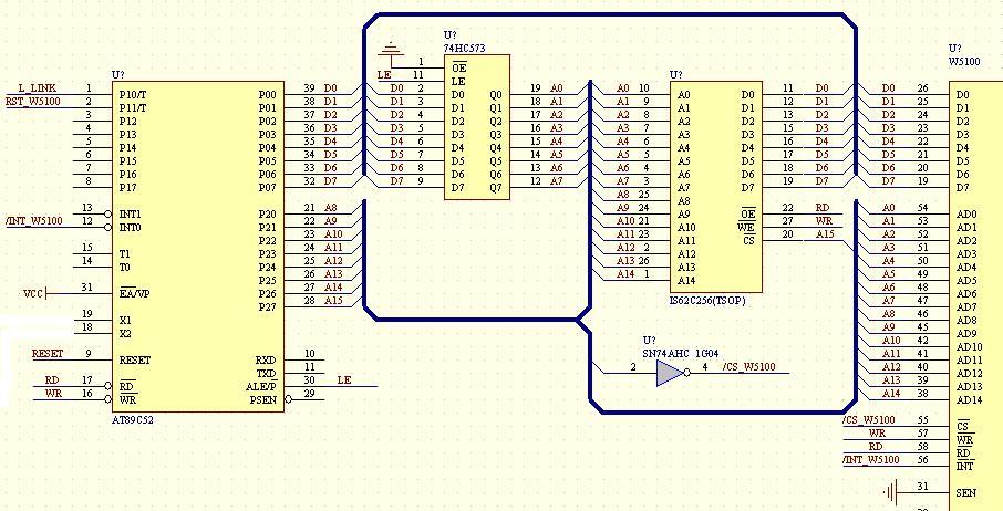
The connect interface between W5100 and MCU is parallel bus interface (If you want to use SPI interface, W5200 is recommended). The following is one of example which is using AT89C52.
External expansion one 32K SRAM (IS62C256) by follow the above image’s hardware interface. Address line A15 as SRAM’s CS(chip select) signal. Therefore 32K XDATA address range is 0×0000~0x7FFF. W5100 as external interface and mapping to 89C52 XDATA range, address line A15 inverting (74AHC1G04) as W5100’s CS(chip select) signal. Therefore the address range of W5100 is 0×8000~0xFFFF. If use indirect bus interface, the address line A2~A14 must need to connect GND for guarantee the initialization of indirect bus interface.
Reset signal
The most important hardware design of W5100 is reset signal and user often ignored. Most engineers adopt RC reset. Although it can be reset, in fact the result is not good.
If not well reset of W5100, it will let some component can’t work, especially Physical layer of Ethernet can’t work and also affect MCU can’t initialize W5100.
The best reset method is using MCU’s IO to output the reset signal. It can be guarantee the synchronization of W5100 and MCU. Even it failed, MCU also can control W5100 easier.
If MCU don’t have enough IO for output the reset signal and user can adopt reset IC(ex.IMP809T). It can guarantee the reliable reset. But user should care about the operating synchronization issue when develop the MCU software.
How to connect network transformer or RJ45

HS-MAG1201 is one of RJ45 (embedded transformer). TCT and RCT is the center tap of HS-MAG1201’s receive side and transmit side. Center tap should be connected to 3.3V. Many engineer will ignore this part when design.
In the other hand, the metal case of RJ45 will be better for not connect to the power GND. If possible, please connect to frame GND. The PCB wiring of TXOP/TXON and RXIP/RXIN should be same length and parallel wiring.
Resistor of RSET_BG
The resistor for connect to W5100 pin 1(RSET_B) should be use 1% precision resistors.
It will be have some unexpected debugging trouble when you use normal precision resistors (5%) for mass production.
Inductance
The inductance of digital power to analog power is very important. If the current pass from inductor is large relatively and the quality of inductor is weak, it will generate DC voltage drop and AC noise and affect the work of W5100 seriously.
A lot of engineer also faced this issue when they start the development. If not suitable inductor, you can remove the inductor and use wire to short circuit directly.
Crystal oscillator
The problem of crystal oscillator is easier to be happened and it is hard to solve.
The common problem for the crystal oscillator of W5100(W5300 and W7100 is same as W5100)as following:
1. The offset of crystal oscillator is larger, far from 25MHz;
2. Oscillation amplitude is not enough, the maximum amplitude of XTLN and XTLP just only a few hundredmillivolts.
If it has above phenomenon, the problem should be come from crystal oscillator. The following is the parameter which shows in the datasheet by WIZnet.

The normal waveform and amplitude of W5100’s XTLN as following:

The normal waveform and amplitude of W5100’s XTLP as following:

COMMENTS