The 6-port E1.31 bridge is a device that allows your PC to communicate with a large number of Renard or DMX controllers using regular Ethernet network connections. It replaces multiple DMX or RS485 dongles with one configurable device that can be mounted in an enclosure in the yard and only requires one Ethernet Cat5 cable (or WIFI) back to your pc or home network. It allows up to 6 DMX universes or Renard networks to be easily controlled from your sequencing software with a minimum amount of wire from your show pc to your controllers. The bridge works with all Renard, DMX and LOR (using DMX) controllers.

The 6-port E1.31 bridge is a device that takes in an E1.31 stream from your network and converts (or ‘bridges’) that to multiple DMX or Renard output streams. E1.31 or sACN (Streaming Architecture for Control Networks) is a method of multiplexing multiple DMX streams over your network using unicast or multicast UDP packets. The 6-port bridge currently supports multicast and unicast streams. Multicast makes it simpler to configure but has drawbacks in very large configurations (10’s of streams). E1.31 can support 63,999 DMX streams or ‘universes’ (64000->65536 are reserved) so it has a virtually unlimited amount of expansion available.
The 6-port bridge can handle up to six E1.31 universes, each of which get directed to a particular port. By default the bridge is configured to send universe ‘1’ to port number 1, universe ‘2’ to port number 2 and so on but you can assign any of the 64k universe numbers to any port if you wish. The bridge takes in the particular universe stream and either outputs it directly out each port for DMX output or it performs a conversion to Renard protocol. The protocol used depends of course on what you plan to use for controllers on the ports that you have configured. You can configure any mix of DMX and Renard protocols to any port.
The bridge has another feature so that each physical output can be re-wired to support either a “standard” DMX RJ-45 electrical output or a Renard electrical output without resorting to making custom cables to support either. The output of the bridge is always RS-485 in either case. Note that regardless if your Renard controller is running standard Renard/Serial code or Renard/DMX code, the jumpers should always be configured for Renard since the physical interface does not change.
How does the 6 Port E1.31 Bridge work?
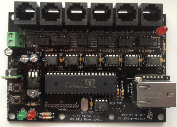
As mentioned above, the bridge takes in a multicast E1.31 UDP stream, determines which stream belongs to which port (if any) and sends that data out the appropriate port. The E1.31 stream enters the bridge via an Ethernet port on the Wiz820io module and is converted to a serial signal that is sent on to the Propeller microcontroller chip. Your sequencer or streaming tool sends multicast packets with an address of 239.255.<UHB>.<ULB> where UHB is the Universe high byte and LHB is the Universe low byte. As an example, the address for universe ‘1’ would be 239.255.0.1. This is why using multicast addressing can be simpler to configure since this address is always the same for any device using that universe. The disadvantage of using multicast is that the packets are sent to every device on the subnet regardless if they are destined for it or not. This means the receiving device must read in the header for each packet or have the means to block these within hardware. Depending on the device and the number of universes of data sent it can swamp the device and possibly end up causing a loss of data. Note however that this is not an issue for most networks until you get into the dozens of universes so it’s not an issue for most users.
Unicast is another method of sending E1.31 packets. For this method, the IP address used to manage/configure the device is also used for the data packets. In this case, the packets are sent directly to the device instead of being broadcast across the entire subnet.
The Parallax Propeller microcontroller determines if the address matches one of the configured ports universe numbers and if it does, reads in the entire DMX stream and sends them out that particular port either as-is or after conversion to Renard protocol. The Propeller chip is quite powerful, it is essentially eight separate microcontrollers in a single package. These internal processors or COGs as they are called can each run completely different (or the same) code. This allows you to partition different functions to different COGs within your code. For more information on the Propeller, visit the Parallax site.
For the bridge, the COGs are used to support both the multiple input processing as well as the six port output processing.
E1.31 Networking Basics and Setup
For more information about how E1.31 works and how you wire up the IP networking side of an E1.31 Network look at E1.31 Protocol
Revision History
6 Port E1.31 Bridge Parts
To build the E1.31 Bridge, you need 4 things:
- The PCB
- The parts to solder on the board, also known as a BOM (Bill Of Materials).
- A power supply to power the board. The board can use any 5-24VDC power supply.
- An enclosure to mount the finished board in. Commonly used enclosures include the CG-500, CG-1000 or the CG-2000 which are available from several vendors
The BOM parts needed to build the board are:
| Mouser BOM | |||
| Part ID | Mouser PN | Description | Qty |
| R1-R3 | 291-220-RC | Carbon Film Resistors – Through Hole 220ohms 0.05 | 3 |
| R4-R9 | 291-120-RC | Carbon Film Resistors – Through Hole 120ohms 0.05 | 6 |
| R10-R12 | 291-10K-RC | Carbon Film Resistors – Through Hole 10Kohms 0.05 | 3 |
| C1-C3 | 140-REA470M1VBK0611P | Aluminum Electrolytic Capacitors – Leaded 35V 47uF 20% 6.3x11mm | 3 |
| C4-C12 | 581-SA105E104MAR | Multilayer Ceramic Capacitors MLCC – Leaded 50volts 0.1uF 20% Z5U | 9 |
| IC1 | 619-P8X32A-D40 | 32-bit Microcontrollers – MCU DIP pkg Propeller Chip | 1 |
| IC2 | 579-24LC512-I/P | EEPROM 64kx8 – 2.5V | 1 |
| IC3-IC8 | 511-ST485BN | Buffers & Line Drivers Hi-Spd Lo Pwr Trans | 6 |
| IC9 | 579-24AA025E48-I/SN | EEPROM 2K 256 X 8 1.8V SERIAL EE, IND | 1 |
| X1 | 520-HCU500-20X | Crystals 5MHz 20pF | 1 |
| Wiznet | 950-WIZ820IO | Ethernet Modules W5200 & MAG JACK ioPLATFORM MODULE | 1 |
| LED1 | 604-WP7113GD | 604-WP7113GD | 1 |
| LED2-LED3 | 604-WP7113ID | Standard LEDs – Through Hole HI EFF RED DIFFUSED | 2 |
| VR1 | 580-OKI78SR5/1.5W36C | DC/DC Converters 7.5W 24Vin 5Vout1 1.5A SIP Non-Iso | 1 |
| VR2 | 511-LF33CV | Low Dropout Regulators – LDO 3.3V 0.5A Positive | 1 |
| Heatsink | 532-577202B00 | Heat Sinks TO-220 HORIZ/VERT SLIM CHANNEL STYLE | 1 |
| S1-S2 | 653-B3F-1000 | Tactile Switches 6X6 Flat 4.3mm Btn Force 100g w/o Grd | 2 |
| IC Socket 1 | 575-199640 | IC & Component Sockets 40P TIN PIN TIN CONT | 1 |
| IC Socket 2 – IC Socket 8 | 575-1104331610003000 | IC & Component Sockets 8P DIP SOCKET SOCKETS | 7 |
| JP1 | 571-826629-3 | Headers & Wire Housings 3P SINGLE ROW | 1 |
| H1 | 571-826629-4 | Headers & Wire Housings 4P SINGLE ROW | 1 |
| Wiznet 1×6 Header | 517-9601066202AR | Headers & Wire Housings 6P STR SR BDMNT SKT 3.0MM TAIL/7.1MMBODY | 2 |
| 2×3 Output Selector | 855-M20-9980345 | Headers & Wire Housings 03+03 DIL VERTICAL PIN HEADER GOLD HT | 12 |
| TB1 | 571-2828372 | Fixed Terminal Blocks 5.08MM PCB MOUNT 2P | 1 |
| J1-J6 | 571-5556416-1 | 571-5556416-1 | 6 |
| Output Shunts | 517-9691020000DA | Headers & Wire Housings 2.54MM SHUNT | 25 |
You can buy the parts directly from Mouser: Click here for Mouser Direct Project BOM or The BOM is also available at a discount in a kit that includes the PCB from DIYLEDExpress.com
Building the 6 Port E1.31 Bridge
The 6 Port E1.31 Bridge requires a fair bit of soldering so take your time and ensure you install the components in the correct orientation when required. Start by sorting the components by type and values. Look over the PCB before starting noting the location of the various components. Follow the standard procedure of installing the lowest profile parts first and ending up with the tallest.

Sourced by http://www.doityourselfchristmas.com/wiki/index.php?title=E1.31_Bridge
COMMENTS