details

How many times have you pulled out of your driveway and gotten ten minuets down the road only to begin second guessing if you actually closed your garage or not? Problem solved! With this instructable you can check if your garage is closed or open and close or open it your self from anywhere in the world… Lets get started!
Step 1: Materials

The great part about this project is that if you’re surfing instructables.com you probably already have most of the parts required!Materials– Bread board
– Jumper Wire
– Alligator Clips
– Small Diode (I used a 12V, 21mA one this should be fine as long as your garage door opener isn’t running on a car battery)
– NPN Transistor (I used a 2N2222 but might vary a little based on your garage door opener)
– Small switch (I harvested this from an old printer)
– Arduino (I used a mega but any will work)
– Ethernet shield (Mine is from Seeedstudios)
– A garage door opener that works with your garage
Step 2: Hardware Setup


This circuit layout is pretty simple and serves as a great introduction to transistors too.First – We want to take apart the opener. The two important things to look for are the battery terminals and the button that you press to open/close the door. First we are going to short the button, I did it with just a length of jumper wire but you can solder the contacts together as well. Next remove the battery and alligator clip or solder some jumpers to the positive and negative terminals.Second – Set up the transistor as shown. A jumper to pin 7 should go through a diode then into the base. We will be sinking the load so plug the emitter into your ground bus.Third – For simplicity I used the same battery that came with the opener. Tape/solder some jumpers to it and connect it to the voltage and ground busses on your bread boards.Fourth – Connect the positive terminal of your opener to the positive bus on your board and connect the negative terminal of the opener to the collecter on your transistor. Stack your ethernet shield and plug the base into pin 7 on the arduino.
Step 3: Software Setup


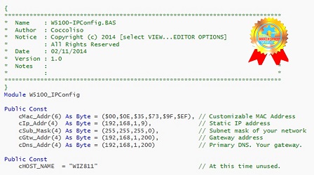
Attached is the sketch you need to run on your arduino. However there are a couple caveats…1. You must plug in an IP adress that is within range on your router (if you are going through a router). To find this follow the more specific commented instructions in the code but basically comment out the manual IP setup code and comment in the DHCP code. This will print an automatically configured IP into the serial. If you don’t know your range you can use that dynamically assigned IP by typing it into the manual IP setup area as you can be sure that is within your router’s range.2. To control the garage door take your now static IP address and type it into your web browser. Following the IP with either /?C, /?O or /?R will either close, open or give the state of your garage door. The /?C and /?O really do the same thing just with a different HTML reply. For /?R to be accurate you must configure the switch, more on that later.3. IF YOUR ARDUINO IS CONNECTED TO A ROUTER READ THIS. If your ethernet shield is going through a router the IP address given is a local IP and therefore the closing/opening in browser maneuver will only work from a device that is also connected to that router. To circumnavigate this you need to forward port 80 to the arduino. This is very different for each router but http://portforward.com/ is a great help when trying to figure this out. After you have completed the port forwarding you can control the arduino by using your global IP instead of the arduino’s local IP. Keep the local IP in the sketch but find your global IP by going to http://www.whatismyip.com/ with any computer connected to your router. You can now type this IP into the browser of any device (on your network or otherwise) and use the same commands to control the arduino. Keep in mind your global IP may not be static and may change as your DHCP lease expires. Google how to assign a static global IP for your router or just keep up to date with the changes if this is the case. This part can be a little confusing if you’re new to this stuff but I am happy to try to help if you have any questions.
Step 4: Final Thoughts

At home this summer I had a need for way to control my garage door from greater distances than just a couple hundred feet. This was the most beautifully simple solution I could come up with and it has worked much better than I expected! With that said there is certainly room for some improvement. The hardware and software to detect the status (open/close) of the door was never fully implemented but in theory it should all work fine. Also you could certainly use a relay in place of the transistor if that is more your taste. I’m happy to hear about any improvements you make to the hardware and sketch so please comment with your ideas and revisions. If you need any help with my version, please comment and I’ll get back as quick as I can!
Here is a video of the project in action! Sorry for the hasty production of it, I’ll try to put together a better video when I’m back home from school.
Happy making! 🙂
COMMENTS