
This adaptor allows you to easily use gigabytes of SD card flash memory and/or a Wiznet WIZ820io ethernet module with Teensy 3.0 or 3.1.
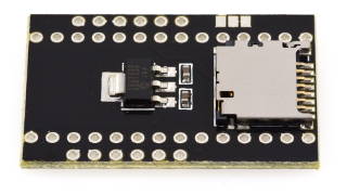
Teensy 3.1, Pins, and WIZ820io are sold separately.
The WIZ820io can be purchased from Mouser Electronics, Digikey, Saelig and other electronic component distributors. PJRC does not sell the WIZ820io ethernet module.
Recommended Assembly Steps
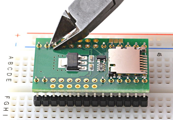
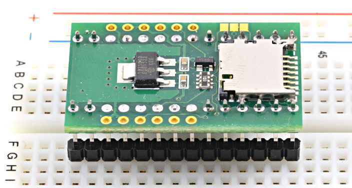
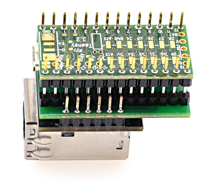
Place the header pins in a breadboard or other fixture to hold them straight and at the correct spacing. Position the WIZ820_SD_ADAPTOR on the pins.
Trim the 12 inner pins next to the WIZ820 pads.
Solder the 28 header pins to the WIZ820_SD_ADAPTOR.
Solder the 12 WIZ820io pin to the WIZ820_SD_ADAPTOR.
Optionally, the WIZ820io pins can be placed into sockets and the sockets soldered to the WIZ820_SD_ADAPTOR, to allow the WIZ820io to be removed.
Solder the 28 header pins to Teensy 3.1.
Optionally, the header pins can be placed into sockets and the sockets soldered to the Teensy 3.1.
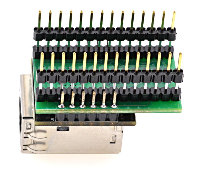
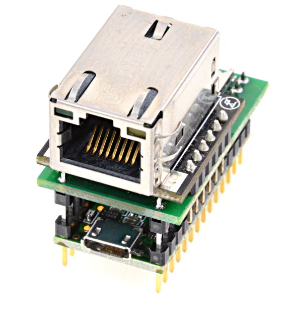
After assembly, the stack of boards should look like this:
Electrical Connections
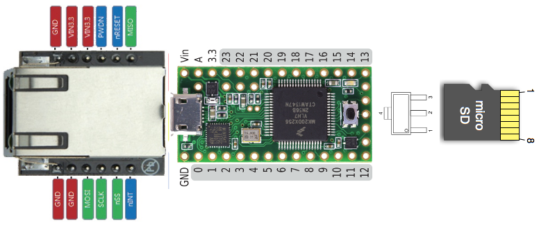
This table lists the electrical connections on this adaptor board.
The WIZ820io and SD card are connected to the default pins used by the Arduino Ethernet and SD libraries. For the SD library, pin 4 should be used in the begin() function.
Teensy3   SD Card   WIZ820io      MCP1825     JUMPER PADS
-------   -------   --------      -------     -----------
 4        2:CS
 8                                             Left Side
 9                  RESET
10:CS               SS
11:DOUT   3:DI      MOSI
12:DIN    7:DO      MISO
13:SCK    5:CLK     SCLK
VIN                               1:IN
          4:VDD     VIN33,VIN33   3:OUT
GND       6:VSS     GND,GND,GND   2:GND+TAB   Right Side
                    PWDN                      Center
By default, the center and right side of the jumper pads are connected, which keeps the WIZ820io powered up. For low power applications, the pads can be cut apart and the left+center joined to allow pin 8 to control the WIZ820io powerdown feature.
Chip Select Pins During Initialization
Some SD cards can be sensitive to SPI activity while the Ethernet library is initilized before the SD library.
For best compatiblity with all SD cards, these 3 lines are recommended at the beginning of setup(). Pins 4 and 10 will be reconfigured as outputs by the SD and Ethernet libraries. Making then input pullup mode before initialization guarantees neither device can respond to unintentional signals while the other is initialized.
void setup() {
  pinMode(4, INPUT_PULLUP);
  pinMode(10, INPUT_PULLUP);
  delay(1);  // allow time for both pins to reach 3.3V
Sourced by https://www.pjrc.com/store/wiz820_sd_adaptor.html
COMMENTS