details
The Sleep n’ Tweet is basically just an Arduino with an Ethernet shield that keeps track of your vitals (movement + heart rate) as you sleep. hehaven’t push it nearly as far as it could go, think of it more as a working prototype than a polished product – but the potential is huge! It could be used to track vitals at any time and tweet anything you want according to whatever filters you put on it. It could be manufactured to be very, very small. And it could also be stuck to just about anything to check for movement and IR or flow changes – but for now we’ll stick to sleep.
Arduino
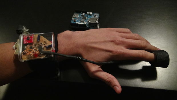
For this project he used the Arduino Uno and an Ethernet shield on top of this. You need to make sure that pins 12 and 13 (point to pins in picture) are open because these will be used for communications between the Arduino and the Ethernet shield. Which sucks because pins 12 and 13 are my favourite to use. he don’t know what it is about them just like the numbers, but that took me 30 minutes to find out. So he used pin 9 to control whether or not the Infrared LED and red LED are active and he used pin 8 to read whether or not there was a change in the IR photo transistor. Pins A0, A1 and A2 were used to take care of the accelerometer. For power, he connected the 5v pin to the heart rate circuit and connected the 3.3v pin to the accelerometer circuit. That is basically how he hooked up the brains of the device. Still plenty of pins open for other things, maybe a moisture sensor to see if you’re sweating buckets in your sleep. Or a pressure sensor to see if you’re crushing a limb for hours and hours every night.
Heart Rate Sensor
The heart rate sensor is comprised of an op amp connected to an IR LED and an IR photo transistor. In short, the design works by shinning an IR LED onto your finger and receiving some amount of light through the photo transistor. When your heart pumps blood, the volume of blood in your finger will change, and so will the amount of light picked up by the photo transistor. This value change will be pretty small so we’ll need to kick the change up a couple of notches with an op amp. The one he have set up should roughly multiply the signal by about 10 000 times. Now what we can do with this amplified signal is pump it into the Arduino and read the changes as ones and zeroes. I’ve also hooked up a LED between the Arduino and the op amp so you can directly view the signal going into the Arduino. What he have done is measured the time in between heart rates and after 5 beats, he take the average to compose a beats per minute. He also have filters in place in the program to rule out any unreasonable frequencies. For example, if the heart rate comes out to be 100ms between beats, he know this reading is false because the human heart cannot beat 600 times per minute. He made the valid range 30BPM to 250BPM. He found the IR sensor works on multiple parts of the body, but best on the finger.
Accelerometer
he used an accelerometer pre-assembled from Sparkfun called the ADXL335, but you can build your own which isn’t that hard.(The schematic is here ) The accelerometer is directly hooked up to the analog pins of the Arduino. Constant readings are given about it’s orientation and he basically he detect the changes in the orientation and log them as movements. He had to do a couple of things in the program to combat irregularities such as twitches. He take a time frame in which the number of movements read is compared to the number of non-movements read. Then, he also change the sensitivity. So if you move by 5 it will detect a positive movement. Basically, more movement equals a higher change in number.
Put it all together and you have a way of reading someones heart rates and movements. Lets move on to what you actually have to get to build this bad boy.

COMMENTS