General Description
The W5100 interface driver provides a simple software driver for using the WIZnet W5100 iEthernet controller with a PSoC (Programmable System-on-Chip) project. The driver can be customized to support many system configurations, and allows for SPI port sharing. Both the SPIM and the SCB interfaces are supported to allow the driver to support many hardware configurations of the application.

Features
- Compatible with PSoC 3, 4, 5, and 5LP
- SPI port independent (Uses Either SCB or SPIM)
- Supports TCP, UDP, and ARP
- 4 simultaneous protocol Sockets
- 2K off-processor packet buffer per socket
Future Plans (Driver version 2)
- Multiple device support
- W5200 / W5500 will be supported
- What’s new in Version 2
- GitHub (alpha version)
- Simple/Advanced configuration Parameters
Source code (GitHub) : https://github.com/e2forlife/PSoC-W5100-Driver/tree/Release-1.2
Evaluation
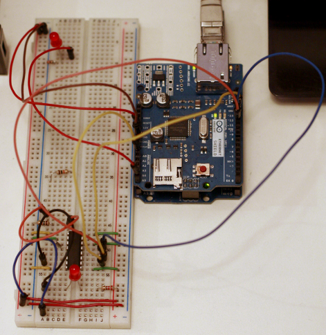
Hardware Connection
I mainly use the PSoC Pioneer (PSoC 4) and the FreeSoC Explorer (PSoC 5LP) as test beds for component development, and for the W5100, there happens to be a handy Arduino shield (Ethernet Shield, $38 Digikey) available so no hand wiring today.

For the PSoC 4, just plug the shield in to the Arduino compatible pins on the the Pioneer board (making sure that you’ve soldered in the 6-pin SPI connector), however, the PSoC 5LP setup takes a little more effort since the Explorer does not have the Arduino 6-pin SPI interconnect. So, we just jumper wire from the MISO, MOSI, and SCK pins on the 6-pin socket of the Ethernet Shield to The P4 connector I/O of the explorer.
| Signal | PSoC 4 | PSoC 5LP |
|---|---|---|
| CSn | P3[4] | P5[2] |
| SCK | P0[6] | P0[6] |
| MOSI | P3[0] | P3[0] |
| MISO | P3[1] | P3[1] |
Project Setup

Once the hardware is set up (or your custom board is built), you need to add the e2forlife_W5100.cylib to the project workspace and set it as a dependency for your PSoC Project. This is simply accomplished by selecting File->Add->Existing Project… from the PSoC Creator menus, or by right clicking the work-space and selecting Add->Existing Project...

Once the driver library project has been added to the work-space, right click the application and select “Dependencies…“. When the dialog opens, select Components check-box for the E2ForLife_W5100 user Dependencies.
Firmware
Setting up the firmware using PSoC Creator (currently 3.0) is a snap. Just switch to the community tab, and expand the Communications/Ethernet tree. For the PSoC 5LP, drag the “E2ForLife – W5100 (SPIM mode)” macro from the right hand selector and place it on the schematic sheet.

(PSoC 4 Users:) On the PSoC 4, there are two options available. The “E2ForLife – W5100 (SCM Mode)” Macro will utilize the new SCM hardware blocks within the device, and the “E2ForLife – W5100 (SPIM Mode)” Which will utilize UDB SPI Master Mode implementation of the interface.
Configuring Component Options
In order for the PSoC to properly communicate with the W5100 the SPI component needs to be configured to operate in 8-bit mode 0 or 3 SPI. Depending on the board routing, clock scheme, and environment, the data rate can vary between 8 and 30 MHz. The default configuration set by the macro initializes the SPI device for an 8 MHz data rate.
W5100 Driver options
The W5100 driver is sectioned in to Driver Configuration, Configuration, and Hardware Configuration. These sections are initialized by the macro to default values and the hardware configuration section is set function with the SPI hardware added.
PSoC 4 Note: Using the PSoC Pioneer board with the Arduino Ethernet Shield will require that the SS_NUM parameter be modified when using the SCM mode. SS number 1 is tied to the W5100, not 0. Another big note is that you will have to modify the default SCM settings to enable 2 SS outputs from the module, assign the CSn output to SS1 when making pin assignments.
| Parameter | Description |
|---|---|
| CMD_TIMEOUT | The number of milliseconds to wait for the W5100 command to execute before declaring a timeout |
| INCLUDE_TCP | Flag used to include the code for the support of TCP/IP. Since TCP is directly handled by the device, only minimal code is required for TCP networking |
| INCLUDE_UDP | Include the protocol processing for UDP |
| INIT_DELAY | The number of milliseconds to wait for the device PLL to lock after a reset or power on |
| TIMEOUT | The number of milliseconds before declaring a generic timeout |
| GATEWAY | The default gateway IP address for which the W5100 will be configured |
| IP | The IP Address for the device when operating with fixed IP addressing. |
| MAC | The MAC Hardware Address for which the W5100 will be configured |
| SUBNET_MASK | The subnet mask to be used for Ethernet communications. Typically 255.255.255.0 |
| SPI_INSTANCE | The instance name of the SPI interface. Configure this to be the name of the interface component for the SPI communications interface. |
| SS_NUM | Integer index of the slave select from the SPI interface. This is used for the SCM component interface for PSoC 4 |
Software
For this post, I’m concentrating on getting up and running using the driver, so the application will start, initialize the board hardware, then open a simple telnet server and wait for a connection. Once the connection is established, it will print “Hello From E2ForLife.com” and end.
For this we will use 7 functions from the API. First we will call W5100_Start() to initialize the W5100 device and local driver data. Next we will create and open a socket using the W5100_TcpOpen(), and start a server using the W5100_TcpStartServerWait(). And lastly use the W5100_TcpPrint() to send the data followed by W5100_TcpDisconnect() and W5100_SocketClose() to terminate the connection
1 2 3 4 5 6 7 8 9 10 11 12 13 14 15 16 | int main() { uint8 tcpSocket; /* * First the SPI peripheral must be initialized * so that the W5100 driver has hardware to use * for the chip initialization that will * occur next */ SPIM_Start(); /* * The next section initialized the W5100 to * default settings setup in the component * configuration dialog. */ W5100_Start(); |
The startup and in initialization section of the code mainly performs only 2 functions in this case: Start the hardware, Start the driver amp; initialize the W5100 registers. The hardware initialization is executed using the Cypress API call for the SPIM component (or the corresponding SCB for PSoC 4). Following thisW5100_Start() is called from the W5100 driver API. This function initializes the internal RAM used by the driver and configures the hardware registers within the W5100.
1 2 3 4 5 6 7 8 9 10 11 12 13 14 15 16 17 18 19 20 21 22 23 24 25 26 27 28 29 30 31 | for(;;) { /* * Now that the W5100 is initialized and configured, * open a socket, and start a server and wait for * connections until the */ tcpSocket = W5100_TcpOpen( 23 ); /* * If the socket was opened the socket number * will be in the range of 0 – 3 to reflect * the socket that was used within the W5100 */ if (tcpSocket lt; 4) { /* Wait for server connections */ W5100_TcpStartServerWait( tcpSocket ); /* Send the string to the remote terminal */ W5100_TcpPrint(tcpSocket, “\x1b[2JHello From E2ForLife.com\r\n”); /* * Wait for the string string to transmit * over the network before closing */ CyDelay(10); /* Disconnect from client (drop connection) */ W5100_TcpDisconnect(tcpSocket); /* Close the socket */ CyDelay(50); W5100_SocketClose(tcpSocket); } } |
Within the main loop, the socket is opened, a servers is started, output is transferred, and the the connection is terminated. First, the socket is opened through a call to W5100_TcpOpen() with the active port passed as a parameter. In this case, we used the Tcp port 23, since we are going to start a telnet server. The next step in this simple application is to start a server and wait for connections. Since we are not doing anything of value while waiting, I used the simple API call W5100_TcpStartServerWait(), which will start a server on the open socket passed, and wait for a connection to be established.

Once the connection has been established, the API call will return, allowing the application to send it’s string using theW5100_TcpPrint() call to send a string (ASCII-Z style) to the remote client using TCP. After that, we just close the connection gracefully by disconnecting (W5100_TcpDisconnect), and then close the socket to free the socket to be opened for another function using theW5100_SocketClose() API call.
So, there you have it… A very simple Telnet server using the W5100 driver.
Check out the source repository here.
COMMENTS