details
This tutorial is about uploading Arduino Shield p/g using WIZ810MJ.

Progress (chronological order)
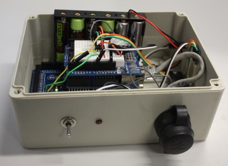
- Connected the 3.3V from the Arduino to pin 24 (VCC) on the WIZ module and Gnd from the Arduino to pin 23 (GND) on the WIZ module. Initially, the orange LED glowed but after a power disconnection (mis-wiring?) it ceased to glow. But after plugged in a cable from the module to an Ethernet switch both the green link LED and orange LED glowed.
- The connector on the module is 2mm pitch—used 2mm jumpers from a scrapped floppy drive and breadboard jumper wire to connect to the Arduino.
- When using no connections other than power, connecting an Ethernet cable to the module appears not to generate any traffic tethereal could detect.
- Connected cable to /RESET pin. By doing a “manual” reset (/RESET switched from HIGH to LOW to HIGH again by the sophisticated “move-wire” method) it seems to get both orange (ready?) and green (link) LEDs.
- Being able to read registers!! By connecting /RESET, SCLK, MOSI, MISO and SS (along with VCC & GND) I was able to successfully read register values. (SPI_EN was left unconnected.)
- Writing registers, configuration for networking and responding to pings work! Plan to upload code soon. Wireshark capture:

Source : http://code.rancidbacon.com/LearningAboutArduinoWIZ810MJ.
COMMENTS