This is a project-report of Indiana University–Purdue University Fort Wayne(IPFW).
This report details the entire design process to achieve the goal of providing the cooling unit with wireless monitoring and control capability. This report will include the conceptual design, building phase, testing phase, and evaluations and recommendations. The conceptual design section will define the specific goals of the project as well as the calculations. The building phase section will display and discuss the design and the implantation of individual parts into the cooling unit. The testing phase section will discuss the various tests conducted. The evaluations and recommendations section will discuss the effectiveness of the implementation as well as recommendations to improve the design.

The self-enclosed system is depicted in above. In this design, both the DAQ system and control scheme are implemented in the microcontroller on the Arduino board. The user inputs of heat load and desired temperature will be transmitted wirelessly using the Wi-Fi protocol to the microcontroller. The sensor readings from the different transducers are fed directly through A/D converter to the Microcontroller which would transmit the sensor readings to the Tablet. All of the calculations necessary for controlling the pump and fan would be done in the microcontroller and the output commands would be fed directly through a D/A convertor to the fan and pump accordingly.
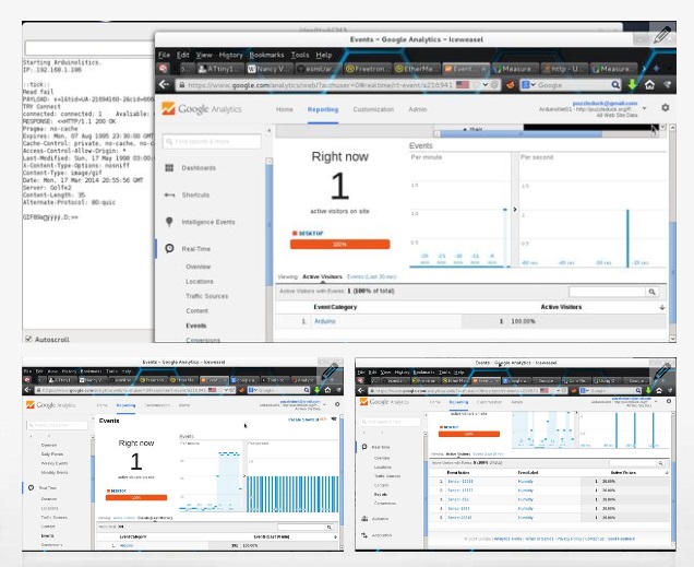
It shows screenshots of selecting a desired temperature and heat-load and temperature chart as below.


And it shows the placement of the Wi-Fi shield(WizFi210) on the Arduino board and the wiring connection from different sensors as below.

About WiFi Shield
The main reason that the WiFi shield EiFi was selected is because of the fact that it allowed for communication even with an Enterprise encryption network such as IPFWs’. The problem we overlooked is that IPFW has many different sub-networks, or subnets, set up and because the WiFi shield and the tablet had to be on the same subnet at any given time, it seems that any shield would have sufficed. We had to buy a separate router to ensure that both the shield and the tablet were connected on the same network whether it be at IPFW or Parker.
Another problem that could occur is that because the Wi-Fi shield was given a static IP, there could be problems if that same IP were to be given to another device. A solution around this could be that because the LCD screen is still intact, it could be possible to use a dynamic IP address and display the address to the LCD screen for the user to plug in themselves.
Source : http://www.ipfw.edu/dotAsset/60bca76d-0ab0-4d10-aedf-f0d79f9345cf.pdf
(http://www.ipfw.edu/departments/etcs/depts/engr/capstone/projects.html)
COMMENTS