This is the tutorial about the web based room monitoring system that can be the internet of things by using Arduino Ethernet Shield.
- Project Introduce
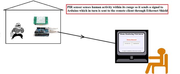
– Room Monitoring System with using Arduino Ethernet Shield which has a built-in WIZnet chip (W5100)
– Be able to detect a Human Activity by the use of PIR(Passive Infrared) sense which does sense human body.
– Be able to transmit information to a remote client through Ethernet Shield.
- Project Feature

<Original Image : http://www.instructables.com/file/FAZ2VPUI4SCW14P>

<Original Image : http://www.instructables.com/file/FGF9VNDI4SCW14S>
– Project background
“Before beginning we should know what we are going to do.
The two images will make you understand about How the system works.
when the door is initially closed there is no human presence hence no infrared radiation. also the light intensity is low, so no unusual activity.
But when the thief actually opens the door, there is a spurt in the light intensity(caught by LDR), and change in infrared radiation(the PIR sensor knows) and this information is sent to a remote client.”
– How to make the connections

“Connecting the wires may be a little bit tricky at times, I have used an LDR and LED for serving up as light detector and source of light respectively, in one go…
But for simplicity sake, I would suggest you to make it one after another, then summing them up will be child’s play(those who know working with Arduino won’t find it trickier).
Connect the GND wire to GND pin slot.
Connect the VCC wire to the 5 V pin slot.
Connect the output wire to PIN 2 slot with a 10 Kohm resistor.
I have shown the required connection in the diagram, you can find more convenient to follow it from there.”
– Complete Connections

“Here’s the diagram involving all the components(the PIR sensor, LDR and LED).”
Source : http://www.instructables.com/id/Web-Based-Room-Monitoring-System-using-Arduino/
COMMENTS