WizFi250-EVB can be used not only for evaluation of WizFi250 module but also for Arduino WiFi Shield. Below information is very helpful for you when you use WizFi250-EVB for WiFi Shield.
Hardware Configuration
1. Check if WizFi250 operates in SPI mode
- WizFi250-EVB can be connected to Arduino board using SPI. Therefore, you need to check the operation mode of WizFi250.
- The first interface signal after factory default decides the operation mode of WizFi250. If the first signal is SPI, WizFi250 will operates as SPI.
- For the factory default of WizFi250, press the function button three times consecutively.

- You can also perform the factory default using AT commands. When you use the AT commands, be careful that you don’t have transmit any UART data after factory default.
- – The default operation mode is set as UART for WizFi250
- – Connect the WizFi250-EVB with PC using USB cable. The USB port is used for UART interface
- – If you input below commands, WizFi250 will be reset with factory default

- – After then connect WizFi250-EVB with your Arduino Board
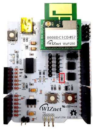
2. Check the position of the 0ohm resistor in WizFi250-EVB

After checking about points, download the WizFi250 Arduino Library. You can get it from WIZnet Github
To check WizFi250 SPI Signal
Preparation for SPI Signal check
1. Connect the Arduino and WizFi250-EVB
2. To use Oscilloscope, connect the cables to SPI pins (MOSI, SS, SCK, MOSO,GND) as below

The general SPI waveform
When SPI Data is input, SS(CS) is asserted as low & SCK(CLK) frequents 8 times. Then the SPI data is transmitted using MISO & MOSI as shown in below figure.


The waveform when WizFi250 transmits the data to host MCU

Example code for SPI test
#include <Arduino.h>
#include <SPI.h>
#include <IPAddress.h>
#include "WizFi250.h"

#define ARDUINO_MEGA_2560

WizFi250         wizfi250;

//The setup function is called once at startup of the sketch
void setup()
{
// Add your initialization code here
    Serial.begin(9600);
    Serial.println("\r\nSerial Init");

    wizfi250.begin();
    wizfi250.setDebugPrint(4);
    wizfi250.hw_reset();

    wizfi250.sync();
}

// The loop function is called in an endless loop
void loop()
{
        while(1);
}
When input data is distorted or Arduino is reset
When you use Arduino Uno board with WizFi250-EVB, you can find the problem that Arduino board is rebooted without reason or serial data is distorted. This problem seems related to small SRAM size of the Uno board. When we try to print a bulk of log messages, we can see the wrong message is printed and the Uno board is rebooted. It seems the SRAM is overflowed.
As you see below, Uno board supports 2KB SRAM & 32KB Flash memory. Considering the space for bootloader, you can use 31.5KB Flash memory.

If you save the log messages into Flash memory instead of SRAM, you can solve above problem. For this, use PROGMEM macro. (You also use this way for other AVR MCUs)
#include <avr/pgmspace.h>

prog_char DBG_Start_Msg[] 		        	PROGMEM = "DBG>>>>";
prog_char DBG_SPI_SEND[]			       	PROGMEM = "SPI Send";
prog_char DBG_SPI_RECV[]			        PROGMEM = "SPI Recv";
prog_char DBG_ERROR_DATA_SIZE_TOO_BIG[]		        PROGMEM = "Error : send-data-size if too big";
prog_char DBG_ERROR_RX_BUFF_OVERFLOW[]	        	PROGMEM = "Error : m_spi_rx_buffer overflow";
prog_char DBG_ERROR_NOT_FOUND_SUCCESS_STRING[]          PROGMEM = "Error : Timeout or Not Found Success";
prog_char DBG_NEED_SPI_NULL[]				PROGMEM = "Need SPI_NUL";
Great post, you have pointed out some great details, I likewise conceive this is a very good website.