How I created a simple home automation project to control multiple power outlets using an Arduino Mega microcontroller.
Highlights of this project.
- Reduce the amount of systems left on standby and ultimately reduce the amount of wasted energy.
- Remotely control the power state of multiple devices.
- Power on and off a media server by using the Power button on the front of the computer.
- Control a collection of radio frequency (RF) devices, including single sockets and power strips.
- Control a couple of Power Distribution Unit’s (PDU).
- Collect and present power state information via a web page that is iDevice mobile friendly.
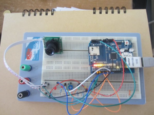
- Control all the above using a single Arduino Mega with an Arduino Wiznet Ethernet Shield.
List of parts
- Arduino Mega
- Ethernet shield
- 433MHz Transceiver and receiver
- Energenie Trailing Gang with Four Radio Controlled Surge Protected Sockets
- Opengear IP PDU
- Breadboard and a few jumper cables
- 2N2222 NPN bipolar junction transistor
Step 1. Directly connected PC
I thought it would be interesting to use a remote method to power up and shutdown a PC by directly connecting to the power button. I opened the case and popped the power switch out, on inspection it was clear that this is just a little push switch. I cut into the cable and added an electrical block connector and gave a quick test to confirm I could power it on and off by simply connecting these two wires. As I wanted to have an Arduino create the connection I decided to use a 2N2222 transistor as I had a couple of these already, you could just as easily use a relay. The connections were as follows:
| Pin (flat side to front) | Name | Arduino |
| E – Left | Emitter | Ground |
| B – Middle | Base | Signal (from Arduino) |
| C – Right | Collector | Power |
Step 2. Energenie RF Power Sockets
Capture the RF code and Configure the Arduino with the RF transmission


| Switch | ON | OFF |
1 | 4314015 | 4314014 |
2 | 4314007 | 4314006 |
3 | 4314011 | 4314010 |
4 | 4314003 | 4314002 |
| ALL | 4314013 | 4314012 |
Step 3. IP PDU’s
I needed to have the Arduino do the authentication to the IP PDUs I needed to form an HTTP GET request with the username and password encoded.
I used the website http://www.motobit.com/util/base64-decoder-encoder.asp which allowed me to encode the default credentials, for example
Username:snmp
Password:1234
Concatenated with a colon join: snmp:1234
Base64 encoded string: c25tcDoxMjM0
To complete the example, below is a code sample of one of the functions I use to collect state information from the PDUs. This clearly shows the use of the authentication code:
client.print("GET /");client.print(powerState);client.print("s.cgi?led=");client.print(LEDCode);client.println("0000000000000000");client.print("Host: ");client.println(hostname);client.println("Authorization: Basic c25tcDoxMjM0");client.println("User-Agent: Arduino Sketch/1.0 snmp@1234"); |
Step 4. The Web Portal/Server
The Web server solution I used is to have the unique information about these devices within an array and then loop through them to build the page for each client request. This made the code a little more complex, but allowed massive reductions in the amount of code I needed to store within RAM.


Source code: https://github.com/jfrmilner/Arduino-PowerSocketControlWeb
Tags: 201303, home automation, pdu, 433mhz transceiver and receiver, arduino mega, ethernet shield, W5100, web server
COMMENTS