This project adds the Ethernet & Tweeting capabilities to the GE 45142 Choice-Alert Wireless Control Center Alarm system. The alarm system supports up to 16 different sensors across 4 zones. By using Arduino & Ethernet Shield, you can add the alarming tweet function that keep informing you of its status.  For this project, below parts are mainly required
– 1 x GE 45142 Choice-Alert Wireless Control Center with Door or Window Sensor Kit from Amazon, Lowes or Home Depot ($30 -$40)
– 1 x Arduino UNO from Adafruit ($30)
– 1 x Arduino Ethernet Shield from Adafruit ($45)
– 1 x 9V regulated DC wall-power adapter from Adafruit ($7)
– 1 x Arduino Project Enclosure from Sparkfun ($12)
– 1 x Right Angle Male Header strip from Sparkfun ($2) – Length of Cat 5 cable
– Heat shrink tubing
The author explains how you can build the project in 6 steps.
Open the Control Center Case


Remove the 4 screws holding the Control Center case together then remove the 2 screws holding the circuit board onto the case. Be careful not to pull of the antenna or speaker wires.
We are interested in the LED leads protruding from the bottom of the circuit board.
Prepare the Control Center


From my testing it appears the Control Center sends roughly 3.3 volts to each LED continuously on the anode and then sinks the current on the cathode when it wants to light up the LED. To read the state of the LED we will connect a wire to the anode and monitor it using an Analog pin on the Arduino. When the LED is not lit we will read about 3.3v and when it is lit we will read little < 0.5v or no voltage as the current sinks through the LED.
Once the case is opened we need to solder 7 wires onto the Control Center circuit board. 1 wire for each of the 6 LEDS and 1 for ground. For the LEDs we are going to solder the wires onto the pin of each LED that is farthest away from the edge of the circuit board. Be careful not to bridge the connection between the two pins when soldering. For the ground we will need to flip the board over and solder it to the outer pin of the barrel jack.
Try to keep the wires as short as possible and route them along the edge of the board to the side with the antenna. After soldering, drill a hole through the back of the case and feed the cable through as shown.
It’s helpful to write down which wire is connected to which LED.
Connect the Arduino


Slide some heat shrink tubing over the cable then break off a row of 6 right angle headers and solder the 6 LED wires to them. Once soldered cover the wires with hot glue for insulation then add and shrink some additional tubing to cover. This will provide a good solid connecter for plugging into the Arduino. Be careful when shrinking over the hot glue as it will remelt if it gets too hot. Repeat the same process for the ground wire with a single header then slide the heat shrink tubing up the cable shrink everything together.
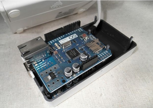
Since the Arduino project enclosure doesn’t really allow for much to be added above and beyond the Ethernet shield we need to make a few modifications to it. We need to remove the 6 female header block from the analog pins and also clip off one of the GND pins. Once completed plug in the Control Center cable and stack the Ethernet shield on top.
In order to connect with Tweet, he uses a proxy server, “ThingTweet from ThingSpeak”. The code is also based on use of “ThingTweet”
You can get more detail about this project and source code from below link. http://www.instructables.com/id/AlarmingTweet/?ALLSTEPS
Tags : 201106, Arduino Ethernet, W5100, Tweet
COMMENTS