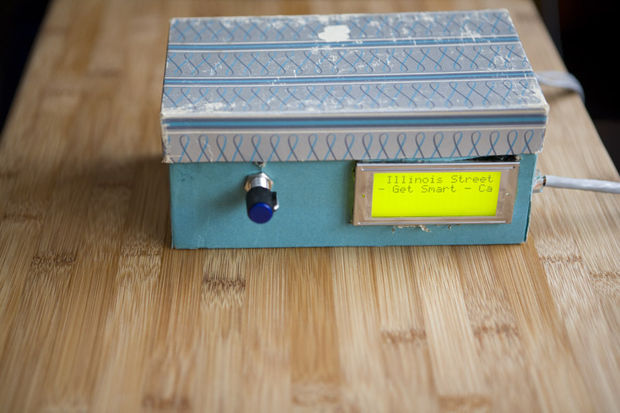
This is an update to Standalone WiFi Radio Control Panel , which enables it to tweet the currently playing song and station. The project is based on an AdaFruit Boarduino, an Arduino-compatible microcontroller platform, with an Ethernet shield, an LCD, and a rotary encoder.

For the Controller :
* Arduino-compatible microcontroller platform (such as Arduino UNO , I used myBoarduino )
* Arduino Ethernet library compatible network controller (such as the Arduino Ethernet Shield )
* LCD Character Display (16×2 characters, or larger, such as this one from Adafruit , I got one from Ebay )
* Absolute Rotary Encoder (mine has 10 positions) (for choosing the station)
* Header pins
* Hookup wire
* 0.1″ female wire connectors of varying degree (optional), which can help when putting everything in the enclosure
* breadboard
* ~7.5-9V wall wart power adaptor

Shematic

Since the LCD and Ethernet Shield together take up so many I/O pins, and since I wanted to leave D0 and D1 unconnected so they wouldn’t interfere with serial debugging, I ended up using 4 of the analog inputs (A0-A3) as digital inputs. To do this, just treat them normally as Digital I/O pins, with A0-A5 corresponding to 14-19 for normal pin operations (pinMode, digitalWrite, digitalRead, etc.).
Source URL : https://github.com/schamp/Schazamp
Original link = http://www.instructables.com/id/Standalone-WiFi-Radio-Control-Panel-Arduino-Power/
Tags : 201102 , W5100, Ethernet shield, Wifi Access point, remote controller
COMMENTS