This is a project to control cars using an Arduino and a Windows Azure service. The Azure service contains an AI speed controller to adjust the running of the cars to prevent them from breaking out of corners and bumping into each other. Also it will adjust the speed for the cars to run faster at the straights and slower in the corners and put a maximum speed on specific cars so trucks will run slower than passenger cars. I’ve split this objective into 3 phases.
Phase I
Run a single car on a simple oval track. Control the speed and gather metric data while the car is running or standing still.
Phase II
Run two cars on the oval track divided into six separate sections. Control the speed of the cars not to bump into each other’s backs based on the gathered metrics.
Phase III
Build a more complicated track with dozens of sections, crossroads and junctions and run half a dozen cars on it. Control the speed of the cars not only not to bump into each other’s backs but also not to bump in to each other at the crossroads and junctions based on the gathered metrics.
Below is some detail on the first phase I completed by now. I’m currently working on the second phase. In this article I’m not going into code details as it’s all plain C++ for the Arduino, C# for the Windows Azure service and SQL for the Sql Azure database.

The service runs in Windows Azure. For logging and collecting the metric data there are a couple of SqlServer Azure databases.

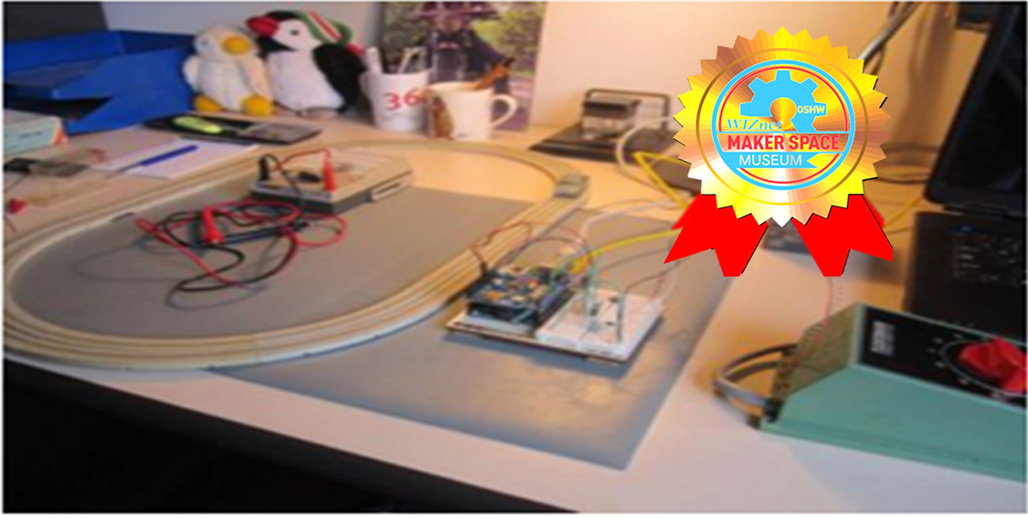
Basic Setup
Faller Ams Track
The Faller Ams track is connected to the Arduino via the electric components. Basic power supply is from an old Fleischmann model train track supplying between 0-17 volts

The Hall effect sensor:

Phase II
Now the track is divided into 6 separate sections, two straights and four 90° curves:

The multiplexer
To drive the 6 sections I’m using a multiplexer. This is an IC component designed to split one lead into multiple leads (demultiplexer) or the other way round to converse multiple leads into one (multiplexer).The Arduino has 6 PWM ports so I could wire each section into one of them. Apart from blowing up one PWM port during my experiments, leaving me with one short, this will also become a problem in phase three connecting dozens of sections. The multiplexer 4051 has 8 ports and is very cheap so this I will use. With 5 PWM ports still functioning this will drive 40 sections and that should be enough for now. The multiplexer sits on the left of the breadboard and on the right are the six MOSFET it controls. Below these are the optocouplers discussed in the next section. When you look closely at the attached video clip you can see the car already slowing down in the curves using this setup.

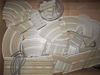
Phase III (Preparation)
I’ll have to look into several issues as preparation for phase 3:
- Design a suitable more interesting track with the track sections I have available
- Expand the available pins either with multiplexers or a bigger Arduino: The challenge will be to do this on a limited budget and without exploding the electronic complexity.
- Refactor the current C# cloud logic to cope with increased complexity
- Create better trace information to monitor the state of the track at any given moment.
These track sections are waiting to be connected:
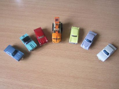
And here are the cars (at least the ones that are still functioning):
For more detail, visit the author’s site.
Source : http://www.codeproject.com/Articles/887003/Control-a-model-car-track-with-Azure-and-Arduino
Tags : Arduino, Azure
Author : Freek Kootstra, info@fkootstra.nl, https://www.linkedin.com/in/freek-kootstra-7878861a, Not yet, wait reply
COMMENTS