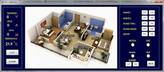
This project is a home automation project that can easily view the status of the house inside. Each room is set up to detect fire, motion, or sound and raises an alarm upon the sensing data. The additional function is to send SMS using RTU MINIUNO. It also shows view your house status via smartphone like following figures.

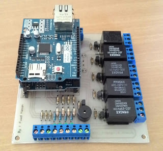
Parts
– 5 Relays
– 1 Buzzer
– PIR
– Arduino Ethernet Shield
– Arduino Uno
RTU can be applied as:
Digital output = control on / off lights, air conditioning, fans, garage doors, etc.
Digital Input = receive the output of PIR sensor (motion), fire sensors, sound sensors, an indication of the MCB trip and so on Other
Analog Input = measuring voltage, current, temperature, and other library sketch
The RTU can be monitored via PC or android phone. Software HMI via PC


##Arduino Source code
#include
#include

#include "Modbus.h"

Modbus Mb;
//Function codes 1(read coils), 3(read registers), 5(write coil), 6(write register)
//signed int Mb.R[0 to 125] and bool Mb.C[0 to 128] MB_N_R MB_N_C
//Port 502 (defined in Mudbus.h) MB_PORT

void setup()
{
uint8_t mac[] = { 0x91, 0xA1, 0xDA, 0x00, 0x52, 0x05 };
uint8_t ip[] = { 192, 168, 51, 10 };
uint8_t gateway[] = { 192, 168, 51, 1 };
uint8_t subnet[] = { 255, 255, 255, 0 };
Ethernet.begin(mac, ip, gateway, subnet);
//Avoid pins 4,10,11,12,13 when using ethernet shield

delay(3000);
Serial.begin(9600);

pinMode(9, INPUT);
pinMode(A0, INPUT);
pinMode(A1, INPUT);
pinMode(A2, INPUT);

pinMode(2, OUTPUT);//buzzer
pinMode(3, OUTPUT);
pinMode(5, OUTPUT);
pinMode(6, OUTPUT);
pinMode(7, OUTPUT);
pinMode(8, OUTPUT);

Mb.R[21] = 1987;
Mb.R[22] = 1006;

}

void loop()
{
Mb.Run();

//Analog inputs 0-1023
Mb.R[0] = (analogRead(A3)*1); // tegangan
Mb.R[1] = (analogRead(A4)*1); // arus
Mb.R[2] = (analogRead(A5)*1); // temperature

//Digital inputs
Mb.C[0] = digitalRead(A0);
Mb.C[1] = digitalRead(A1);
Mb.C[2] = digitalRead(A2);
Mb.C[3] = digitalRead(9);

//Digital outputs
digitalWrite(2, Mb.C[10]);//buzzer
digitalWrite(3, Mb.C[11]);
digitalWrite(5, Mb.C[12]);
digitalWrite(6, Mb.C[13]);
digitalWrite(7, Mb.C[14]);
digitalWrite(8, Mb.C[15]);

}
Source
: http://puaks.blogspot.co.id/2015/11/rtu-miniuno.html
Video
COMMENTS