Have you ever thought of adding an RFID tags/card security system or monitoring system in your home and/or office. Well if you got here i bet you already looked up how freaken expensive they are ranging from $200 to $2000. It is too much.
Now, let’s make a system that would cost under $100 and could do even more than just access a door. A internet enabled arduino rfid tag reader. that for $20 more can open doors.
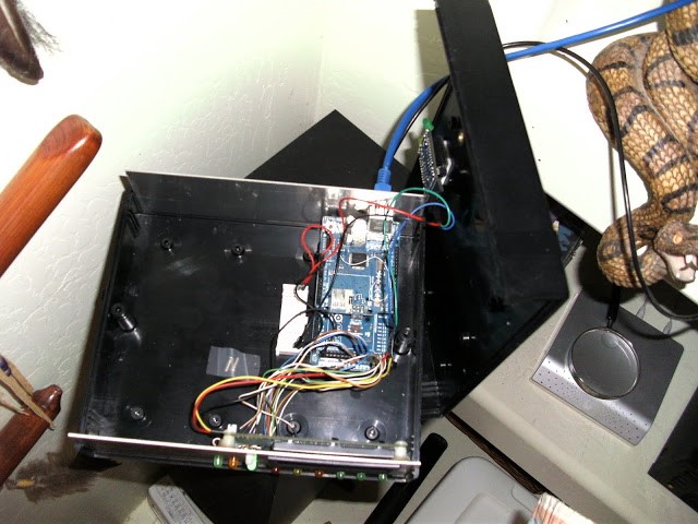
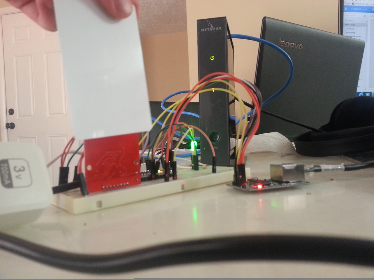
Here is the prototype:
Before we Begin (Necessary)
Before we can start scanning cards and sending them to our Telnet/TCP server we need some libraries Get UIPEthernet here; https://github.com/ntruchsess/arduino_uip
get MFRC522 here; https://github.com/miguelbalboa/rfid
Put both of these libraries in Program Files(x86)/Arduino/Libraries/ Restart arduino
Hardware
- Arduino Nano (You can always modify your code to fit your device)
- MFRC522 with MAIFARE cards
- Jumper wires (Male to Male) (Male to Female)
- enc28j60 ethernet module/sheild
- RGB LED
- 3V OR 5V greater than 700 mileamp AC-DC converter
Setup
- Attach arduino to breadboard (If nano or micro)
- Look up online for the pinout of your board to find the SPI setup(Change values below)
- Connect arduino pin 10 (SS) to ethernet module ss or CS
- Connect arduino pin 12 (MISO) to rfid MISO and ethernet SO
- Connect arduino pin 11 (MOSI) to rfid MOSI and ethernet SI
- Connect arduino pin 13 (SCK) to rfid SCK and ethernet SCK
- Connect arduino pin 9 to rfid RST pin
- Connect arduino pin 8 to rfid SSN
- Connect arduino pin 5 to green led, 4 to blue and 3 to red
- Connect your AC to DC to the + and – on your breadboard
- Ground your arduino to the ac to dc
- Connect VCC and GND on both rfid and ethernet to the ac-dc (REMEMBER THESE DEVICES ARE ONLY 3v!!!!! do not supply 5v) If problem use resistors to bring the voltage to 3v
- Wire VCC pin on LED to the arduino 3v or ac-dc 3v
- Connect ethernet cable to module and make sure it is on the same network as your computer
- Plug USB cable from computer to arduino
- Connect computer to same network
Running the code
- Plug AC-DC power to the wall
- Make sure your arduino is currently connected to the computer
- Make sure both device are on the same network
- Flash your modified arduino code or if the one I have works for you then great(Almost no chance you will have to modify it)
- Start your Python, C++ script or whatever Telnet/TCP server on your network
- Restart your arduino to be safe
- Wait until the light turns blue and try scanning a card, if your server got the ID of the card then your ready to go
- Remember what the lights means Purple/fading red means booting up
- Red means any error such as the card was at a weird angle and/or the server didn’t respond in time
- Green means pass so the server responded with a go and you can read your next card
- Blue means waiting/loading waiting for a card or response
- If your arduino starts to lag out and takes over 30 seconds to show a red light means that the arduino ethernet module couldn’t connect to the server at all. This could be caused by multiple things first your arduino doesn’t have enough power and the arduino ethernet module is struggeling to send a packet or that your computer server isn’t running or that your arduino and computer are not on the same network.
- If your arduino keeps lagging out then try these tricks to fix them
- Turn off windows firewall
- go into advanced firewall settings and allow inbound/outbound port 23
- port forward you router to your computer with port 23
- If you are wireless connect the arduino straight into the router and your computer to the same one
- Buy a more heavy duty AC-DC power adapter
- Else maybe you input your ip address or connecting address wrong
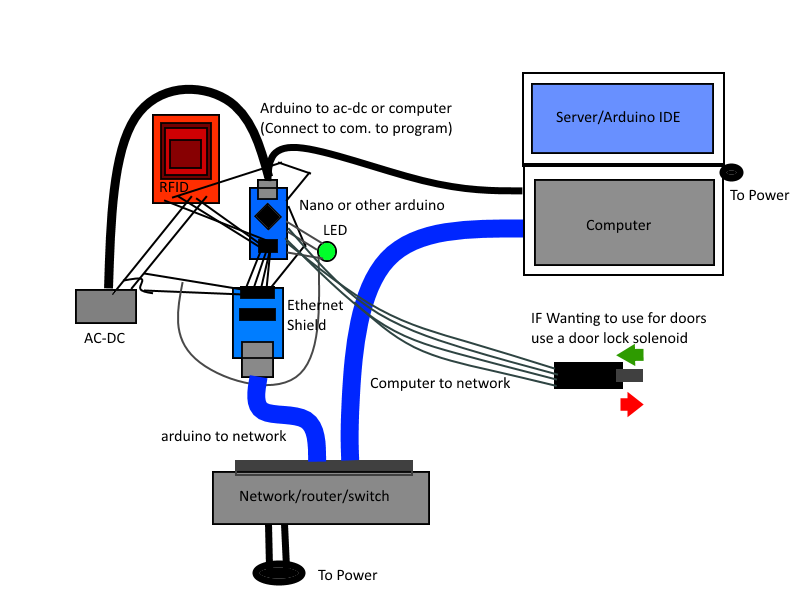
Schematics : https://halckemy.s3.amazonaws.com/uploads/image_file/file/54198/Wiring%20diagram.png
Code : https://create.arduino.cc/code_files/23722/download
COMMENTS