This project started to improve the author’s current technology in searching for injured/trapped firefighters. The current technology is composed of blinking/flashing light & loud alarm system, activated by periods of inactivity/lack of movement & by direct push of button. NO GPS.
Solution: Mobile Gps/radio tracking that allows fallen firefighters to be rapidly located and rescued.
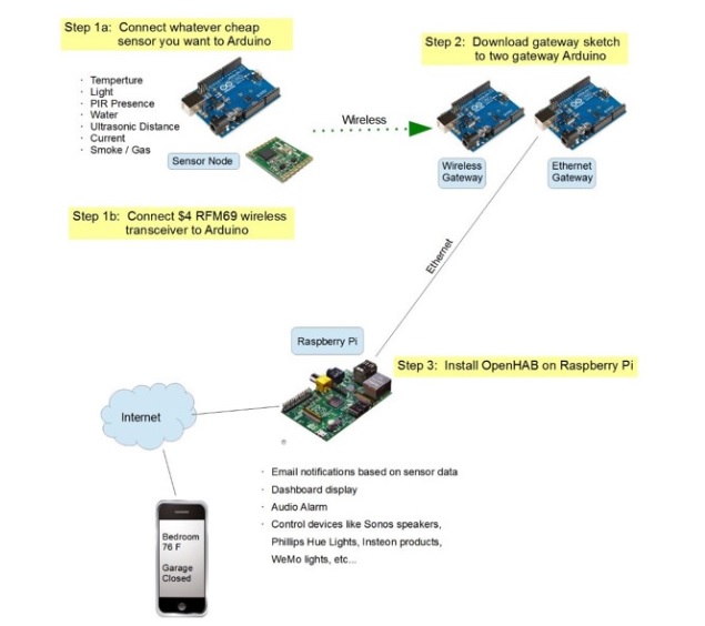
**Arduino, Plus gps/radio sensor to detect location, plus raspberry pi for base station. Pi to be deployed at command post of major incidents, Arduino to be encased in heat/shock resistant housing and attached to firefighting turnout/air pack. Location trackable via cell phone.

Components Needed:
- Two Arduino Uno Clones with 3.3V/5V switch set to 3.3V.
- One Wiznet 5100 ethernet shield
- One RFM69HW w/ wires soldered on
One Arduino will be designated the “RFM Gateway” and the other is the “Ethernet Gateway”. On the RFM Gateway Arduino, wire up the RFM69HW like you see in the wiring diagram at the top of this step.
This is the on-going project in Hackday.io site. For more detail, visit below link
https://hackaday.io/project/11354-improving-firefighter-safety
COMMENTS