Blynk With Arduino
This project is an example of Ethernet shield.
Users can easily manage their house by using Arduino platform through Blynk Platform.
This project is included in category of Remote Control on WIZnet Museum.

Components
-. Arduino UNO
-. Arduino Ethernet Shield
-. Mini Breadboard
-. Green, Red LED
-. 2100 Ohm resistors
-. Jumper wires
-. Cat5 Cable for Ethernet
-. USB cable
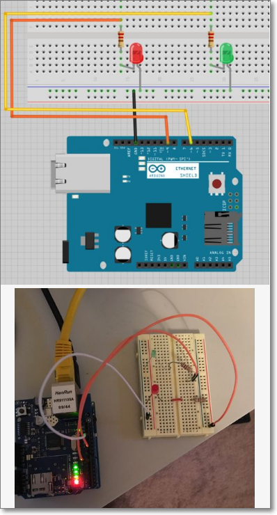
Wire It Up


I ran jumpers from ground, pin 9 and pin 6 to the breadboard and placed the resistor(s) between the + (anode) and the signal jumper.
Code It .. Sort Of


Create a new project in the Blynk app on your phone (download it first of course) . Add a button and set it from the default of “push” to switch. The set the output pin ( I used pin 9 for the red LED ). Add a slider and associate it to your pin. Make sure it’s a PWM pin ( I used pin 6 for the green LED ) I turned off the “send values on release only” setting as I wanted it to dim in real time.
Click on the nut icon for project settings and send yourself the auth token.
In codebender, I used the appropriately titled BlynkBlink example. The code that matters is as follows:
#define BLYNK_PRINT Serial // Enables Serial Monitor
#include
#include
#include  // This part is for Ethernet stuff

char auth[] = "YourAuthToken"; // Put your Auth Token here. (see Step 3 above)

void setup()
{
  Serial.begin(9600); // See the connection status in Serial Monitor
  Blynk.begin(auth);  // Here your Arduino connects to the Blynk Cloud.
}

void loop()
{
  Blynk.run(); // All the Blynk Magic happens here...

  // You can inject your own code or combine it with other sketches.
  // Check other examples on how to communicate with Blynk. Remember
  // to avoid delay() function!
}
For more information, please refer to the following link;
Source : http://www.instructables.com/id/Blynk-With-Arduino/ипотека онлайн банки.
COMMENTS