Description :
The goal of this project is to be able to view temperature and control pumps from a web page for a home hot water solar system .


The objectives of this project is to :
- Read pt1000 analog RTD sensor for measuring solar panels that can get too hot in case of digital sensors .
- Read 10k Thermistors to accommodate existing equipment (i.e. sensors deep in storage tank).
- Read DS18B20 1-wire bus digital sensors for all other temperature – cheapest, simplest and most accurate.
- Connect any sensor to any function easily.
- Alarm out and stop pumps when it is too cold, or when the storage is at a maximum hot level.
- Use an LCD Display to display main system temperatures; use attached buttons to control operations with simple user input to manually switch pumps.
- Publish Temperatures and Pump Status to a web page and provide the same pump control as available on LCD User interface.

Components required :
- Arduino Mega
- LCD display
- 5V 4 Relay Module Shield for Arduino ARM PIC AVR DSP
- LCD1602 Character LCD Keypad Shield V1.0 for Arduino
- HCY – 6888 9V 1A AC / DC Power Supply Adaptor
- Arduino Compatible Mega 2560 R3 Microcontroller Board EC0365201
- Ethernet Shield with Wiznet W5100 Ethernet Chip Support Micro SD Card NZ0000801
- DS1307 Based RTC IIC / I2C Real Time Clock Module with Calendar NZ0016001

Wiring :
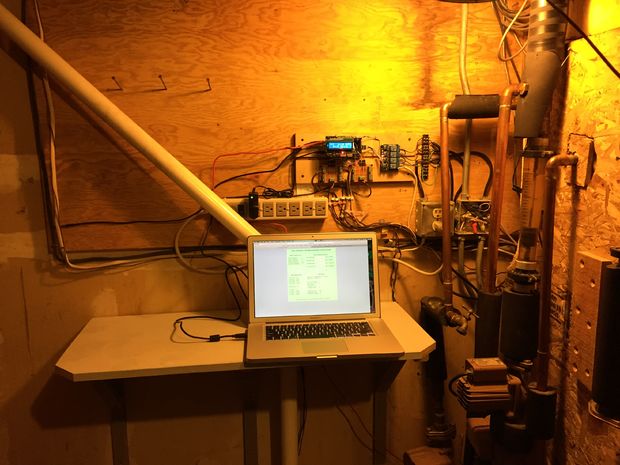
With most of the connections taken care of through plugging the Arudino assembly together, it was very easy to handle all the rest using ribbon cables with female pin connectors on each end . 3 groups of wires handled the 10k sensor board, the Digital/pt1000 sensor board and the Relay board. Wherever male ends are needed to plug into the Mega, as can be seen in the photos, simply used pins cut out of a right angle male header and used a 3pin chunk of male header shorted together to distribute analog reference. The selection of which Mega pins to be used for this were chosen for proximity to where they needed to go and ease of connecting the wires. The following lists are what was chosen and what is expressed in the sketch.
Connections for the 10k sensor board were as follows:
- Ground
- Mega pin A14 – A10k Sensor
- Mega pin A13 – B10k Sensor
- Mega pin A12 – C10k Sensor
- Mega pin A11 – D10k Sensor
- Mega pin A10 – E10k Sensor
- – nc
- Mega pin AREF – Analog Reference
Connections for the other sensor board were as follows:
- Ground – in from Mega
- Ground – out to 10k board
- – nc
- Mega pin AREF – Analog Reference
- Mega pin A15 – pt1000 Sensor
- Mega pin 47 – One Wire Bus for digital sensors
- – nc
- VCC – power from Mega for digital sensors
Connections to the relay card were as follows:
- Ground – in from Mega
- Mega pin 39 – relay 1 control (Panel Lead Pump)
- Mega pin 41 – relay 2 control (Panel Lag Pump)
- Mega pin 43 – relay 3 control (Hot Water Pump)
- Mega pin 45 – relay 4 control (House Heat Pump)
- VCC – power from Mega for relay card
Other than this list, the relays had to be connected to pumps and AC power and the terminal blocks had to be connected to the various sensors. connect up extra sensors that happen to be available and display all values on the web page. A little software ‘patch bay’ provides a place to connect up which physical sensor .
For more detailed information including schematic and source code , look into the main instructable at :
http://www.instructables.com/id/2nd-Gen-Arduino-Hot-Water-Solar-Collector-Controll/
Tags : 201601, Arduino Mega , W5100 Ethernet Shield , LCD1602 LCD Keypad Shield ,Digital Temperature Sensor .
Author : Thorigol .
COMMENTS