components
Hardware Components
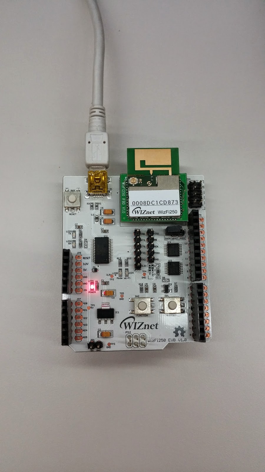
WizFi250-EVB
X 1
Software Apps and online services
Arduinodetails

![]()
WizFi250-EVB can use Arduino Wi-Fi Shield. So you can use Wi-Fi module(WizFi250) more easy with Arduino Board.
This is download URL of WizFi250 Arduino Library and Checkpoint for using WizFi250-EVB with Arduino.
Check Point 1
For using WizFi250-EVE with Arduino, WizFi250 have to SPI mode. This is the method for checking WizFi250 whether SPI mode or UART mode.
- WizFi250-EVB connect to PC using the USB cable and check the version of WizFi250 using the serial terminal program as a hyper terminal on your PC.(If you want to use Arduino, WizFi250 must be more 1.0.0.0 version )

- WizFi250’s interface mode(UART or SPI) are decided due to first input signal after doing a factory default. so you may as well do factory default ones first.
- For doing a factory default, You can press function button on WizFi250-EVE three times. This is a description of Function Pin or Function button.

- If factory default is well done, you can see the message as below.

Check Point 2
For using WizFi250-EVB with Arduino, You have to connect 0ohm register to 1 and 2 of R14.

Check Point 3
This is WizFi250-EVB Pin description for using SPI interface. Data Ready pin indicates that there is data to send through SPI. When WizFi250 has data to send in the SPI mode, this will be changed to a high state. This pin can be used for awakening host MCU.

Check Point 4
if you want to check SPI interface simply, you can use this code.
#include
#include
#include
#include "WizFi250.h"

#define ARDUINO_MEGA_2560

WizFi250        wizfi250;

//The setup function is called once at startup of the sketch
void setup()
{
// Add your initialization code here
    Serial.begin(9600);
    Serial.println("\r\nSerial Init");

    wizfi250.begin();
    wizfi250.setDebugPrint(4);
    wizfi250.hw_reset();

    wizfi250.sync();
}

// The loop function is called in an endless loop
void loop()
{

}
This is the message printed by WizFi250 on serial monitor in Arduino sketch. If SPI interface is well, you can see the message as below.
Serial Init

===== SPI Send =====
AT

==================


===== SPI Recv =====
WizFi250 Version 1.0.0.0 (WIZnet Co.Ltd)
AT
[OK]

==================


===== SPI Send =====
AT+MECHO=0

==================


===== SPI Recv =====
AT+MECHO=0
[OK]

==================
Source: http://kaizen8501.blogspot.in/2014/08/tutorial-for-using-wizfi250-evb-with.html
COMMENTS