Description:
In this Project we will use Arduino and Ethernet shield W5100 to create a simple Web server.Using the Ethernet library, the device will be able to answer a HTTP request with the Ethernet shield. After opening a browser and navigating to the Ethernet shield’s IP address, the Arduino will respond with just enough HTML for a browser to display the data.
Hardware:
Arduino board
Ethernet Shield (W5100)
PIR Sensor
LDR
LED
Resistor 220 ohm.

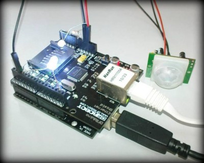
Arduino board and Ethernet shield, we will find 4 rows of header pins (female on main board, while male on shield). They’re designed to be stackable. Plug the Ethernet shield on top of the Arduino main board. Make sure all the pins are aligned and inserted properly to prevent wrong connection. After that connect the sensors and LED as shown in the schematic below. The connection is very straight forward.
First, a 220 ohm resistor is connected in series with the LED and Digital Pin 4 will drive this LED. PIR sensor output digital signal of 5 and 0V. So any digital I/O pin can be used to read the signal. I’m using Digital Pin 3. For LDR sensor, we will read the analog value produced by the voltage divider formed by the LDR and 10k ohm resistor at Analog In A5. The completed hardware will look like the figure below. The hardware setup is really simple, isn’t it? No soldering at all!
You can see that I insert the iron pins of the components into the female header of the Ethernet shield. Sometimes the connections are loose because the iron pins may be too thin for the header. So you may want to extent the pins and plug the components on a breadboard.

Sketch:
Sketch refers to Arduino’s program. It’s the unit of code that is uploaded to and running on an Arduino board. Before we get started with the sketch, we need to install Arduino IDE. It can be downloaded from www.arduino.cc. This Arduino sketch is based on the WebServer.pde example with some modifications to suit our application. The example is located at File > Examples > Ethernet > WebServer in Arduino IDE. Shown below is the Arduino IDE opening the ArduiServer.pde sketch.

First of all, we need to include SPI.h and Ethernet.h at the beginning of the sketch. We’ll use the functions in these two libraries later. Each piece of networking equipment has a unique serial number to identify itself over a network, and this is normally hard-programmed into the equipments’ firmware. However with Arduino we can define the MAC address ourselves. If you are running more than one Ethernet shield on your network, ensure they have different MAC addresses by altering the hexadecimal values in the line:
- byte mac[] = { 0xAA, 0xBB, 0xCC, 0xDD, 0xEE, 0xFF };
However if you only have one shield just leave it be. There may be statistically very rare chance of having a MAC address the same as your existing hardware.
Next we need to specify the IP address of the Ethernet shield. Go to the line:
- byte ip[] = { 192, 168, 1, 111 };
The 192.168.1.111 is the IP address I use for my TM Wireless ADSL modem (Model: Innacomm W3100), so you can alter it to match your own setup. For example, if your home router’s IP address is 192.168.0.1, you will need to set your Ethernet shield IP to let’s say 192.168.0.53 so that the Ethernet shield is able to talk to the router. Hence, your IP address should look like this:
- byte ip[] = { 192, 168, 0, 53};
You can put any number at the forth column. It’s not necessarily to be 111 or 53. Any number will do as long as none of your device connected to the same router is using the same IP address. You may also try pinging your network from a computer connected to the network, and lookup a table. On your computer, click [Start] -> [Run…] and type “cmd” and [Enter]. Type “ipconfig” to find your network address. The network address is found by performing a logical AND operation on your IP address and the subnet mask. You can see I leave this comment at ArduiServer.pde:
- //P1 –> { 10, 1, 1, 5 };
That’s the address I use for my P1 Wimax device. It’s working too!
The last thing we need to set for Ethernet configuration is the port number. Port 80 is the default port for HTTP. Here I use 3178 because it’s the last 4 digits of Cytron’s support line:
- Server server(3178);
Then we define the variables used in the sketch:
- int LED = 3; // led is connected to digital pin 3
- int PIR = 2; // PIR sensor is connected to digital pin 2
- int LDR = 5; // LDR sensor is connected to analog in 5
- int PIRstate = 0; // variable for PIR sensor status
- float photocell = 0; // variable for photocell (LDR) analog value
- char c = 0; // received data
- char command[2] = "<pre class=“EnlighterJSRAW” data-enlighter-language=“cpp”>int LED = 3; // led is connected to digital pin 3
- int PIR = 2; // PIR sensor is connected to digital pin 2
- int LDR = 5; // LDR sensor is connected to analog in 5
- int PIRstate = 0; // variable for PIR sensor status
- float photocell = 0; // variable for photocell (LDR) analog value
- char c = 0; // received data
- char command[2] = "\0"; // command
- }</pre>"; // command
- }
We do the initialization process in the setup section:
- void setup()
- {
- Ethernet.begin(mac, ip);
- server.begin();
- pinMode(LED, OUTPUT);
- pinMode(PIR, INPUT);
- }
- }
After initialization, we write the program in void loop (). Two useful functions that I would like to mention here are:
- client.print(data, BASE); // BASE (optional)
- client.println(data);
These two functions are used to print data or string on the web server page. client.println() will print an end-of-line character, while client.print() will not. To display a webpage in the browser, we need to use HTML coding. So you can see a lot of HTML syntax in void loop ().
You can download the source code from the below link
https://github.com/CytronTechnologies/Arduino_Ethernet-Shield
The LDR reads the light level of the room and show the value as the Light Reading. If there’s no movement detected, the web page shows “No Movement” in green colour. The data will refresh every 5 seconds. By clicking on the LED On and LED Off buttons, you can control the white colour super bright LED connected to the Arduino board. When the LED is turned on, the light reading increases dramatically (from the initial value of 195 to 939). This is because I put the LDR facing the white LED. When the PIR sensor detects movement, the web page will show “Motion Detected!” in red colour.


Motion detection:

More information:
https://tutorial.cytron.io/2011/07/27/an-arduino-room-monitoring-web-server/
COMMENTS