Arduino Ethernet Web Server with Relay

This post shows how to build an Arduino Ethernet web server that controls a relay that is attached to a lamp.
ORIGINAL POST
By https://randomnerdtutorials.com/
components
Hardware Components
Arduino UNO
X 1
recent version
Lamp
X 1
any lamp
details

arduinowebserver.gif

This post shows how to build an Arduino Ethernet web server that controls a relay that is attached to a lamp. You can access your web server with any device that has a browser and it’s connected to the same network.

Ethernet shield

The Arduino Ethernet shield connects your Arduino to the internet in a simple way. Just mount this module onto your Arduino board, connect it to your network with an RJ45 cable and follow a few simple steps to start controlling your projects through the web.

Note: you must connect an Ethernet cable from your router to your Ethernet shield as shown in the following figure.

Pin usage

When the Arduino is connected to an Ethernet shield, you can’t use Digital pins from 10 to 13, because they are being used in order to establish a communication between the Arduino and the Ethernet shield.

Relay module

A relay is an electrically operated switch. It means that it can be turned on or off, letting the current going through or not. The relay module is the one in the figure below.

About mains voltage, relays have 3 possible connections:

  • COM: common pin
  • NOnormally open – there is no contact between the common pin and the normally open pin. So, when you trigger the relay, it connects to the COM pin and power is provided to the load (a lamp, in our case).
  • NC: normally closed – there is contact between the common pin and the normally closed pin. There is always contact between the COM and NC pins, even when the relay is turned off. When you trigger the relay, the circuit is opened and there is no power provided to the load.

The connections between the relay and the Arduino are really simple:

  • GND: goes to ground
  • IN1: controls the first relay. Should be connected to an Arduino digital pin
  • IN2: controls the second relay. Should be connected to an Arduino digital pin
  • VCC: goes to 5V

Configuring your network

Take a look at the configuring your network code snippet:

byte mac[] = {
0xDE, 0xAD, 0xBE, 0xEF, 0xFE, 0xED };
IPAddress ip(192,168,1,XXX);

Important: you actually might need to replace that variable highlighted in red with appropriate values that are suitable for your network, otherwise your Arduino will not establish a connection with your network.

Replace the following line with an IP that is available and suitable for your network:

IPAddress ip(X, X, X, X);

Schematics

Wire you circuit accordingly to the schematic below:

Demonstration

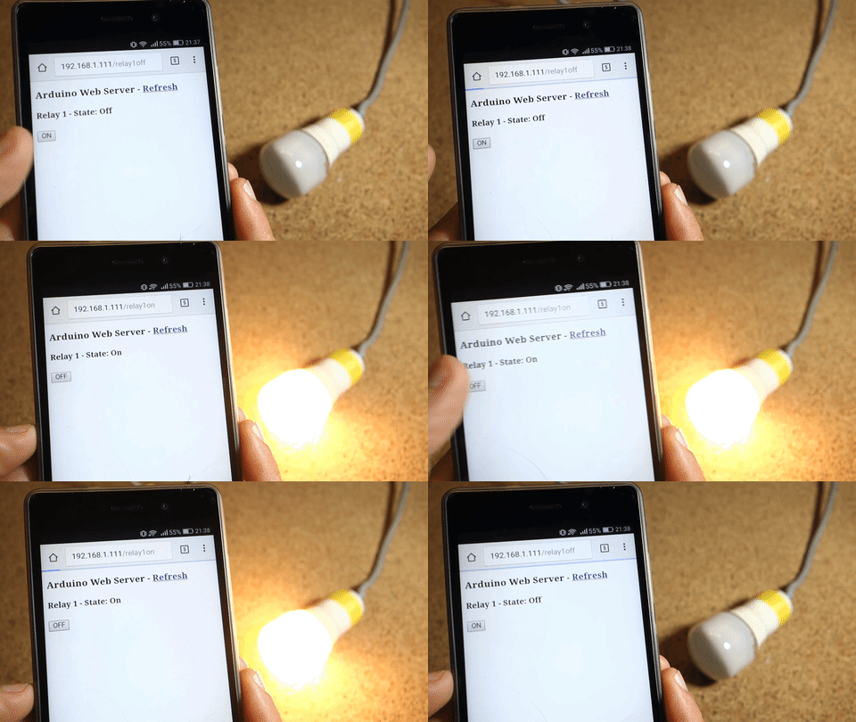
Your Arduino Web server looks like the figure below :

documents
Code
source code
raw code

COMMENTS

Please Login to comment
  Subscribe  
Notify of
POSTED BY