
A few months back I pointed readers to an article by Frank Sautter on adding an Ethernet port to the ESP32 which I found quite interesting. It reminded me that I’d been playing around with a Wiznet wiz820io board a while back on an older PIC-based project, so I pulled it out of the parts drawer and started fiddling with trying to get it working with an ESP8266 module. There were some signs of life, but it was so flaky that I really didn’t quite know whether I had dodgy hardware or whether my graft of the ESP8266 code from the W5100 library to the W5200 library was just crap (the latter being a very strong possibility). It had whetted my appetite though, as I was looking for a means to interface an ESP module to my LAN as an ESP-Now gateway.  So I ended up getting one of the (cheap) newer W5500 modules (the one with the yellow pin header and the “PWOER” LED label)‡ which are popping up all over the place at the moment at about $4 shipped (click on the picture on the right to see the full-size image of the board). The W5500 handles more sockets than the older versions of the chip and is generally recommended for newer designs (it’s a little cheaper, too).
Although the W5500 needed a little tweaking to get going, there weren’t any serious issues with either the hardware or the software and it didn’t take too long to get it working. One issue (which is actually an ESP problem, not a W5500 one) is that the chip-select for the external SPI is actually routed via GPIO15 and, as we pretty much all know from experience by now, that’s one of the “magic” pins at boot-up/reset which changes the way that the ESP8266 behaves. In fact there’s a pull-up resistor on the W5500 (and, as far as I know, all of the other Wiznet modules) CS line which will cause the ESP to drop into programming mode if the W5500 CS line is simply connected directly to GPIO15. The solution to that is quite easy — put a PNP transistor buffer (configured as an emitter follower) between the two. 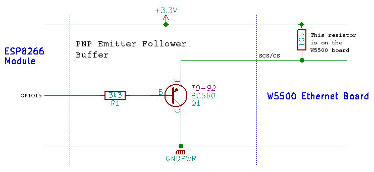 Because of the pull-up on the W5500 board, you don’t need an emitter resistor, but you do need to add a base resistor of somewhere in the region of 3k3 between GPIO15 and the transistor’s base (and the collector of the transistor goes directly to ground). Any small-signal PNP transistor, such as the BC560 or 2N3906 should work in this situation; it’s not that critical. This fix should work for pretty much any SPI connected peripheral board …but you might have to add the emitter resistor if the target board doesn’t already have a pull-up.
The second hardware requirement is that we need to dedicate another, non-SPI GPIO as a reset driver for the W5500. On my test board I used GPIO5. This allows us to hold the W5500 in reset until the ESP has completed it’s own housekeeping and is ready to bring up the network connection. So, with that addition, the pin connects between an ESP8266 and the W5500 are:-
The pin numbering for the NodeMCU boards is given on the left, with the standard ESP8266 GPIO numbers in the centre column. In addition to the data pins shown above, you need to connect ground and either +5v -or- +3v3. The W5500 board has its own, on-board voltage regulator, so a +5v supply is okay, but sharing a 3v3 supply with the ESP8266 is a more likely scenario in our case (the data pins on the W5500 are 5v tolerant, by the way).
On the software side, I ended up using the Wiznet Ethernet Library for the Arduino 1.5.x IDE. It hasn’t been updated in a while …but the last updates were to add the ESP8266 hooks into the code. There are good instructions in the README.md file on how to install and use it, but –don’t– uncomment the “#define WIZ550io_WITH_MACADDRESS” line referred to in those instructions. The normal, cheap W5500 boards do -not- have a built-in MAC address and you must set one manually in software before you can use them.
All in all, it really was quite easy to get the W5500 ethernet board not just connected to my LAN, but also talking to my MQTT broker to both publish and subscribe. Sometime in the next couple of days I’ll try to get around to sanitizing my code to the point where I can throw it up on GitHub as a simple example, but even before then, I’d say this is a safe enough purchase[¹] for anyone who wants to muck around with a wired connection to their ESP8266; you’re not going to break the bank if it doesn’t work as expected.
COMMENTS