
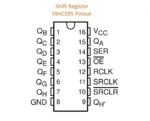
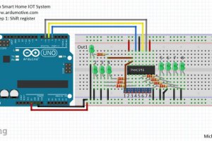
Step 1: Shift Register 595 and Outputs
The shift register will give to your Arduino an additional 8 digital outputs, by using only 3 pins on your board!
Here you can find a simple tutorial with the shift register 595 IC and Arduino uno board.
SR 595 and Arduino uno:
Pin 8 (GND) to GND
Pin 10 (SRCLR’) to 5V
Pin 11 (SRCLK) to Arduino pin 6
Pin 12 (RCLK) to Arduino pin 5
Pin 13 (OE’) to GND
Pin 14 (SER) to Arduino pin 4
Pin 16 (Vcc) to 5V
QA is the first output – QH is the 8th output. We will connect each output with one screw driver – terminal and with an LED through a 220 Ohm resistor.
When you are ready, proceed to the next step.
(tip: You can use the QH’ – pin 9 to add one more shift register ic and expand your outputs.)
Step 2: Buttons and PhotoCell

We will add 8 buttons, but we will use only 2 Arduino pins.
Find here a tutorial with multiple buttons through only one analog pin of Arduino board.
Button BUS line 1 for output 1 to 4 to Arduino analog pin A4
Button BUS line 2 for output 5 to 8 to Arduino analog pin A5
Add a photocell to control a light bulb. It can be an outdoor light that will automatically turn on at night!
Find here a tutorial with a photocell (or photoresistor).
Use one screw driver – terminal here to expand the sensor for the main circuit.
Photocell will be connected to Arduino analog pin A3.
You can now proceed to the next step.
Step 3: Ethernet Shield
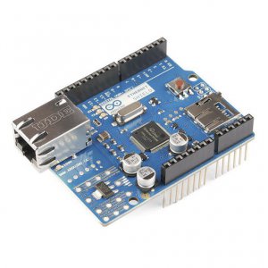
If you have an Ethernet Shield just attached it on the Arduino uno board.
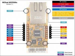
I am using the Wiznet Wiz550io ethernet module. It uses the same library with official Arduino Ethernet Shield (Ethernet.h), the only difference is that it has a unique MAC address.
Some notes about SPI connection:
MOSI – Arduino pin 11
MISO – Arduino pin 12
SCLK – Arduino pin 13
SCSn – Arduino pin 10
Οptionally for Wiz550io
RDY – Arduino pin 7
RST – Arduino pin reset
INT – Arduino pin 2
Note! Wiz550io must be powered from 3.3V output pin of Arduino uno! Do not use the 5V pin with this module!
Step 4: The Code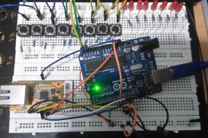
I also made my circuit in an breadboard first to test it.
Here’s the code, embedded using Codebender!
Try downloading the codebender plugin and clicking on the Run on Arduino button to program your Arduino with this sketch. And that’s it, you’ve programmed your Arduino board!
If you want you can make your changes in the sketch below by pressing the “Edit” button. Try for example to change the labels of outputs, for example change “Output1” to “Kitchen Light” (line 164 value=”Output 1″).
You can also change the network ip addresses to fit your network configuration.
Photo cell value (line 29) is setted to 300, but you can also change it by pressing the Edit button.
If you don’t use Codebender you have to manual search and install all additional libraries to your Arduino IDE.
COMMENTS