
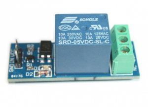
Step 1: What Is a Relay?
A relay, from the external point of view is a simple switch capable of passing current or not. This phenomenon occurs through a physical principle, based on the coupling magnet that is generated through a passage a small excitation current, which is supplied by the Arduino. There are two configurations with regard to the relay:
1. NO (Normally open)
2. NC (Normally closed)
These two configurations differ only in the code you need to write in Arduino. The first configuration, in the case of switching off the relay, no current is passed (the circuit is open) and that the lamp is turned on you need to get out of an Arduino signal “HIGH”. The NC configuration is dual, in case the relay is not energized, the current flows in the device and that the lamp is off, you need to do to get out of an Arduino signal “LOW”.
To recap from the point of view of the code:
NO configuration
digitalWrite(relay,LOW); // Lamp off
delay(1000);
digitalWrite(relay, HIGH); // Lamp on
Configurazione NC
digitalWrite(relay,LOW); // Lamp on
delay(1000);
digitalWrite(relay, HIGH); // Lamp off
For those who wish to learn more about how this circuit element, you can visit the website of Wikipedia, which talks about the various types of relays.
Step 2: How to Connect the Various Cables Between Devices

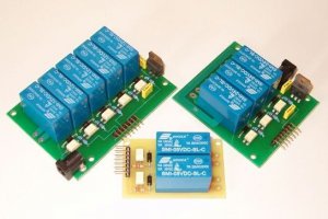
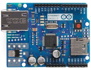
The links that need to be done to make the project are quite simple. We have two devices to be connected to the Arduino: 1) the relay and 2) the Ethernet card.
Concerning the first, it will be necessary power the relay with 5 V, the ground and the pin-out, to be connected to Arduino pin set in the code, which in this case is 5.
The microcontroller Ethernet is slightly a bit ‘more complicated, because they are well connected by flexible cables 6. There are two usual power cables, VCC (3.3 V, though!) And GND and 4, which are used to send and receive data over the Internet. Here is a table that summarizes the connections:
Arduino
Vcc -> 3.3v
GND ->GND
SCK -> Pin 13
SO -> Pin 12
SI -> Pin 11
CS -> Pin 8
Step 3: Software Installation of the Various Components
The functions that allow you to operate your ethernet card is not present in the Arduino IDE. For this reason it is necessary to install this library, inside the folder “libreries” Arduino. To do so, just download the file in. Zip, unzip it and move it to the folder of the Arduino, without opening the program. Alternatively, you can do this procedure directly from the IDE software.
Now that the library is present, we can proceed to load the file on our Arduino Uno.
To do this we download the source code from this link and press the button in the top left, to transfer it to our microcontroller. After a few seconds, if all goes well, will come the message “Loading completed.” Now we can finally go to practice!
/**
Questo codice permette di accendere una lampada connessa al relè da remoto, sfruttando
la scheda di rete ENC28J60
SCK -> 13
SO -> 12
SI -> 11
CS -> 8
Vcc -> 3.3 V
GND -> GND
*/
#include
#define RELAY_PIN 5
#define REQUEST_RATE 5000
static byte mymac[] = { 0x74,0x69,0x69,0x2D,0x30,0x31 };
char* on = “ON”;
char* off = “OFF”;
boolean relayStatus;
char* relayLabel;
char* linkLabel;
byte Ethernet::buffer[700];
void setup () {
Serial.begin(9600);
Serial.println(“Getting IP via DHCP”);
if (ether.begin(sizeof Ethernet::buffer, mymac) == 0)
Serial.println( “Failed to access Ethernet controller”);
if (!ether.dhcpSetup())
Serial.println(“DHCP failed”);
ether.printIp(“My IP: “, ether.myip);
// ether.printIp(“Netmask: “, ether.mymask);
ether.printIp(“GW IP: “, ether.gwip);
ether.printIp(“DNS IP: “, ether.dnsip);
Serial.println();
pinMode(RELAY_PIN, OUTPUT);
digitalWrite(RELAY_PIN, LOW);
relayStatus = false;
relayLabel = off;
linkLabel = on;
}
void loop () {
word len = ether.packetReceive();
word pos = ether.packetLoop(len);
if(pos) {
if(strstr((char *)Ethernet::buffer + pos, “GET /?ON”) != 0) {
relayStatus = true;
relayLabel = on;
linkLabel = off;
} else if(strstr((char *)Ethernet::buffer + pos, “GET /?OFF”) != 0) {
relayStatus = false;
relayLabel = off;
linkLabel = on;
}
digitalWrite(RELAY_PIN, relayStatus);
BufferFiller bfill = ether.tcpOffset();
bfill.emit_p(PSTR(“HTTP/1.0 200 OKrn”
“Content-Type: text/htmlrnPragma: no-cachernrn”
“”
”
”
”
”
“
 ”
””
Controlla la lampada
“
”
), relayLabel, linkLabel, linkLabel);
ether.httpServerReply(bfill.position());
}
}
Step 4: Internet of Things
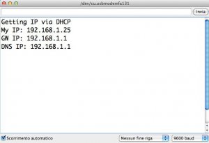

The first step is to get the local ip address of the Arduino. To do this there are several possibilities: the first is to open the serial port, or the other option is to download a program to scan the host in the local network.
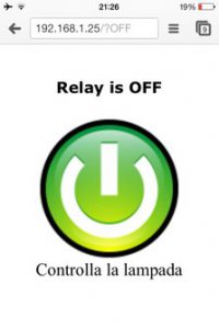
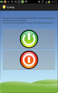
Now that we have the IP address, open the browser and type in our phone its address. You will see a web page like the one in the photo.
Once you press the green button, a new page will appear, with which you can turn off the light.
To turn on the lamp, even remotely, you must open port 80, the control page of our router, choosing the corresponding IP.
Step 5: And for Ethernet Controller W5100 ?
You can complete the project if you have the Ethernet Controller W5100. The correct code is the one in this link. http://ismanettoneblog.altervista.org/blog/lezione-14-come-accendere-lampada-remoto-arduino/
/**
Questo programma permette di accedere e spegnere una lampada da remoto
*/
#include
#include
int pinLED = 9; // pin a cui è connesso il LED
boolean acceso = false;
// Mac Address di Arduino
byte mac[] = {
0xDE, 0xAD, 0xBE, 0xEF, 0xFE, 0xED
};
// Viene inizializzata la libreria Ethernet di Arduino e il webserver gira sulla porta 80
EthernetServer server(80);
void setup() {
pinMode(pinLED,OUTPUT);
digitalWrite(pinLED,LOW);
Serial.begin(9600);
// Viene inilizzato il webserver e la connessione di rete
Ethernet.begin(mac);
server.begin();
Serial.print(“server is at “);
Serial.println(Ethernet.localIP());
}
void loop() {
// Vengono ascoltati nuovi client
EthernetClient client = server.available();
if (client) {
Serial.println(“new client”);
// Finisce una richiesta HTTP
boolean currentLineIsBlank = true;
String postText =””;
while (client.connected()) {
if (client.available()) {
char c = client.read();
if(postText.length()<10){
postText +=c;
}
// Se viene completato l’invio della richiesta HTTP, allora il server invia la risposta
if (c == ‘n’ && currentLineIsBlank) {
// Viene fatta una risposta HTTP, in pratica viene creata una pagina WEB in HTML
client.println(“HTTP/1.1 200 OK”);
client.println(“Content-Type: text/html”);
client.println(“Connection: close”); // Dopo la risposta la connessione si interrompe
client.println();
client.println(“”); // serve per inserire i caretteri speciali
client.println(“”);
client.println(“”);
client.println(“”); // Viene creato il Titolo
client.println(”
Benvenuto nel Webserver Arduino
“); // Viene inserito del testo
client.println(”
Attraverso questa pagina è possibile accendere e spegnere lampada, connessa ad un relè
“);
client.println(“”);
client.println(“”);
break;
}
if (c == ‘n’) {
currentLineIsBlank = true;
}
else if (c != ‘r’) {
currentLineIsBlank = false;
}
}
}
// Se l’utente ha premuto l’icona per accendere il LED
if(postText.indexOf(“?on”) >0){
digitalWrite(pinLED,HIGH);
Serial.println(“Accendi LED”);
acceso = true;
}
// Se l’utente ha premuto l’icona per spegnere il LED
if(postText.indexOf(“?off”) >0 ){
digitalWrite(pinLED,LOW);
Serial.println(“Spegni LED”);
acceso = false;
}
// Viene cambiata la pagina WEB a seconda che il LED sia spento, oppure acceso
if(acceso){
client.println(“ “);
client.println(”
La lampada è accesa
“);
}else{
client.println(“ “);
client.println(”
La lampada è spenta
“);
}
delay(1);
// Viene chiusta la connessione
client.stop();
Serial.println(“client disconnected”);
}
}
Step 6: Android Application !
Now you can use your Android to control in an easy way your lamp remotely !
COMMENTS