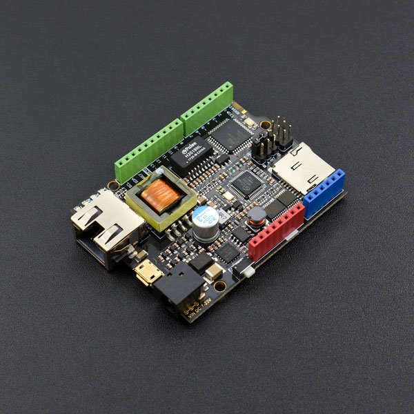
- Microcontroller: Atmel Atmega32u4 (Arduino Leonardo)
- External Input Voltage Range (recommended): 7V~23V DC
- External Input Voltage Range (limit): <24V DC
- POE Input Voltage: 48V AC/DC (802.3af standard compliant PD device)
- Digital I/O Pins: 20
- Analog I/O Pins: 6
- DC Current per I/O Pin: 40mA
- Flash Memory: 32KB (ATmega32u4) (4KB used by bootloader)
- SRAM: 2KB (ATmega32u4)
- EEPROM: 1KB (ATmega32u4)
- Clock Speed: 16MHz
- PHY: WIZnet W5500
- PHY Clock Speed: 25MHz
- Dimension: 73.5x53.5x15mm/2.89x2.11x0.59 inches
- Home network equipment: set-top box, PVR, digital media center
- Serial Ethernet: access control system, LED display, wireless AP relay, etc
- Parallel Ethernet: POS or handheld printer, copier
- USB Ethernet: storage device, network printer
- Security system: webcam
- Monitoring equipment
- Embedded server
Tutorial
Preparation
- Standard POE Protocol Ethernet Swtich X1
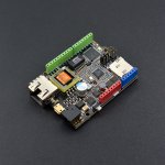
- W5500 Ethernet with POE Mainboard X1
- Micro USB cable X1
- RJ45 network cable X2
Step 1
Connect W5500 Reset pins: Connect A-RST pin to D11. (Default: Connected)
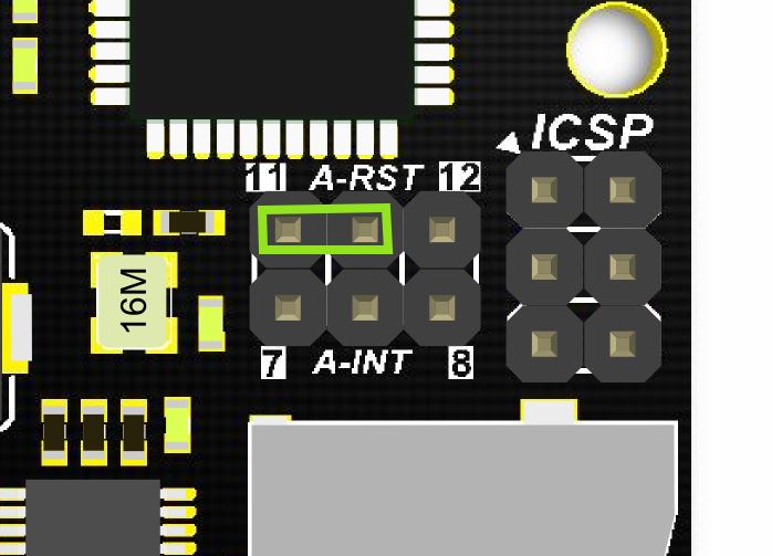
Step 2
Plug one end of the ethernet cable to W5500 mainboard, another end to any LAN ports of the Ethernet Switch, or you can use normal Internet switch or router device to directly connect to a PC’s network interface (the module needs to be powered up here).

Step 3
Connect the W5500 mainbord to a computer with a USB cable.

Step 4
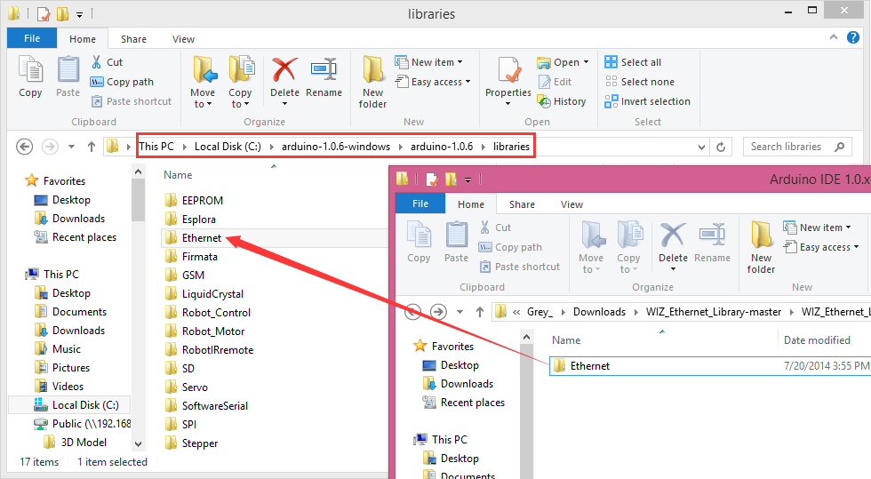
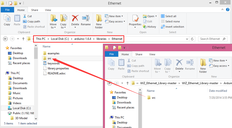
Download the WIZnet official Arduino library here. Unpack the downloaded file and then, place the Ethernet file under Arduino IDE 1.0.x or Arduino IDE 1.5.x in the libraries file of Arduino IDE according to your Arduino IDE version (overlap the original Ethernet library). Open Arduino IDE editor, find WebServer example in File->Example->Ethernet and open it.
- Download the W5500 Ethernet library here
- Replace the existing Ethernet library according to your Arduino IDE version:
NOTE: Good news! You can use arduino IDE v1.7 from Arduino.org that has “Ethernet 2” library, which works with this board. It means you don’t have to download any modded libraries. Thank for the Vladimir Akopyan comments. Welcome to share your projects and comments on the Disqus.
Step 5: Pin Definitions
Note: These parts should be declared at the beginning of the sketch.
1. Define W5500 SPI “SS” pin and “Reset” Pin:
#define SS     10U    //D10----- SS
#define RST    11U    //D11----- Reset
2. Setup function
void setup() {
pinMode(SS, OUTPUT);
pinMode(RST, OUTPUT);
digitalWrite(SS, LOW);
digitalWrite(RST,HIGH);  //Reset
delay(200);
digitalWrite(RST,LOW);
delay(200);
digitalWrite(RST,HIGH);
delay(200);              //Wait W5500
Example
Open Arduino IDE, Select Boards –>Arduino Leonardo and COM port
Check that it works
Open the Arduino Serial Monitor to initialize the setup and you will see some information about the connection processing. Open your browser, input the IP address and you should get see data of 5 virtual analog pins:


COMMENTS