
ABOUT THIS PROJECT
Why Smart Lighting?
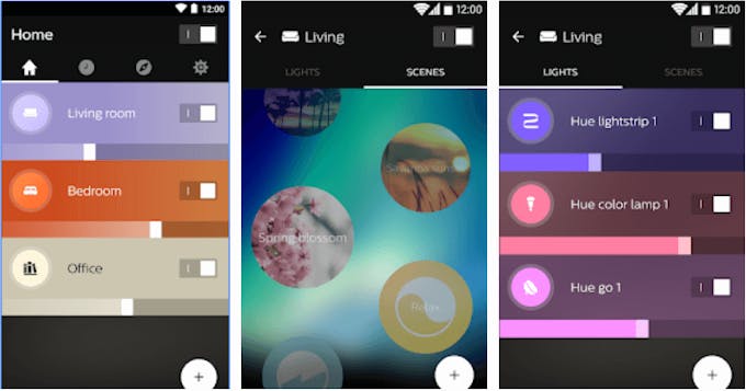
Currently all the smart lighting is mainly controlled using apps, because of the Internet of Things situation, when sometimes no longer have the option of just turning the light on, especially when internet is off. My house is filled with smart lighting system, and just about 2 weeks ago when I couldn’t find my phone, I couldn’t turn any of my lights on.
This guide writes a step by step procedure on how to control your lights the old fashioned way using S2E and Rotary control for brightness.
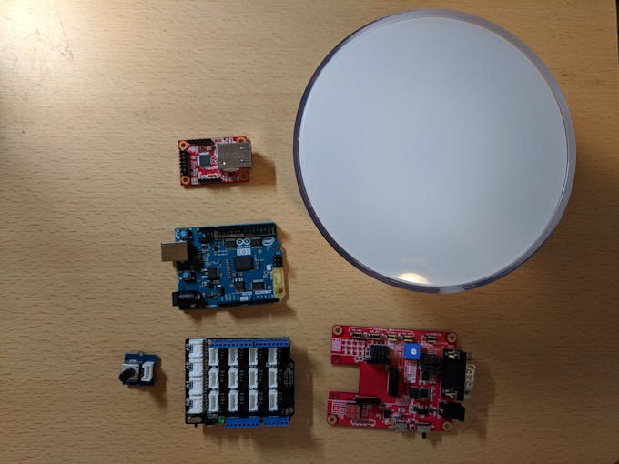
Step 1: Gather Components
Components for this application is very simple and all provided by hackster through 2 different challenges. All you need to purchase is a Philips Hue lightbulb, in this project we will use Philips Hue Go, but any Philips Hue bulb would work.
- Infineon’s 3D magnetic 2GO kit & Rotator Knob
- WIZ750SR S2E Kit
- Arduino Uno or 101
- Seeed Base Shield
- Seeed Rotary Angle Sensor
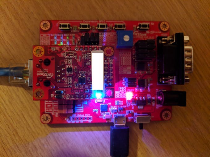
Step 2: Connect the WIZ750SR
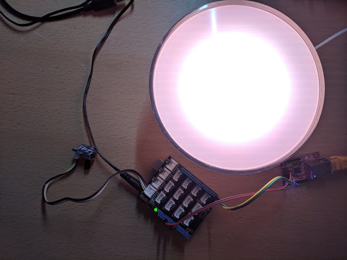
With developer edition, we first can power up the WIZ750SR through micro-usb port. when everything is connected, we should see green LED on for connected to the ethernet, blue LED on for EtherNet add on working and red led on for device being powered on as figure below.
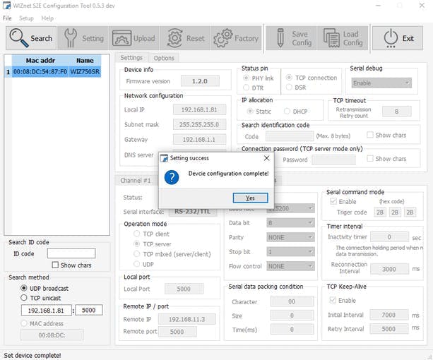
After powering on we can download the configuration tool from https://github.com/Wiznet/WIZnet-S2E-Tool-GUI to check whether the device is working. Easiest way here is to go through IP allocation via DHCP, then go back to static to auto fill out the Network configuration
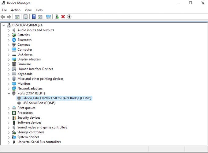
The USB to UART driver can be downloaded if you are using the usb port. The Micro usb port that powers up the board will be the CP210x USB to UART Bridge used for debugging.
https://www.silabs.com/products/development-tools/software/usb-to-uart-bridge-vcp-drivers
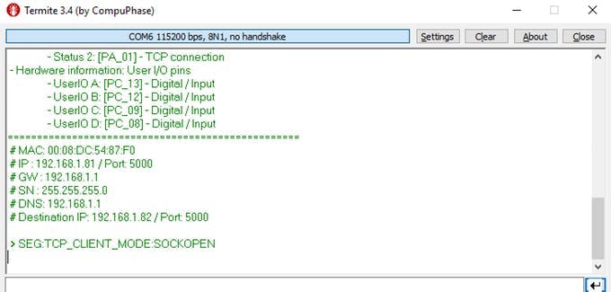
We can use debug port to test out termite to test out the serial port, which can be downloaded from https://www.compuphase.com/software_termite.htm we should receive all the messages sending to COM port via debug usb
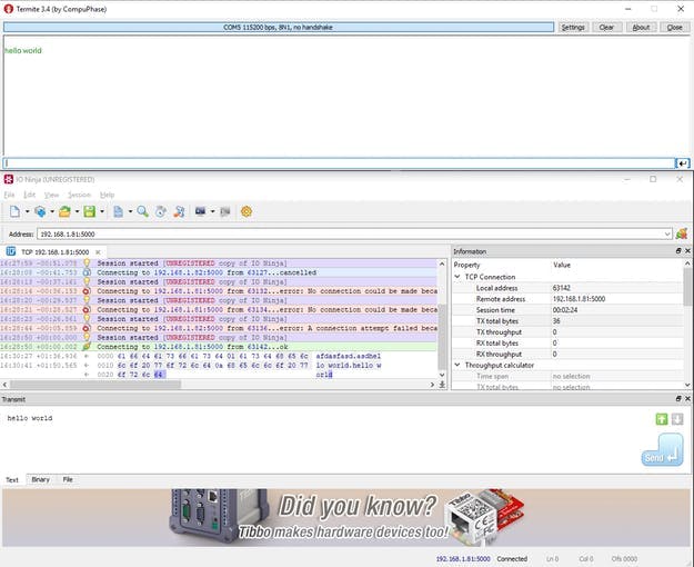
As for the ethernet side we used ioninja’s tcp server listening http://ioninja.com/plugins/tcp-listener.html Once that’s successful we can test out whether these are in Sync, this allows to communicate from Serial to Ethernet
Step 3: Program the Arduino
We first need to get rotary knob to work, using following Arduino code we can easily record it through port A1
#define ROTARY_ANGLE_SENSOR A0
#define LED 3  //the Grove - LED is connected to PWM pin D3 of Arduino
#define ADC_REF 5 //reference voltage of ADC is 5v.If the Vcc switch on the seeeduino
                  //board switches to 3V3, the ADC_REF should be 3.3
#define GROVE_VCC 5 //VCC of the grove interface is normally 5v
#define FULL_ANGLE 300 //full value of the rotary angle is 300 degrees
int incomingByte = 0;   // for incoming serial data
void setup() {
// initialize the LED pin as an output:
Serial.begin(9600);     // opens serial port, sets data rate to 9600 bps
pinMode(ROTARY_ANGLE_SENSOR, INPUT);
pinMode(LED,OUTPUT);
}
void loop() {
  float voltage;
  int sensor_value = analogRead(ROTARY_ANGLE_SENSOR);
  voltage = (float)sensor_value*ADC_REF/1023;
  float degrees = (voltage*FULL_ANGLE)/GROVE_VCC;
  //Serial.println("The angle between the mark and the starting position:");
  Serial.println(degrees);
  delay(100);
}
From here we can get the rotary running.

Step 4: Connect WIZ750SR to Arduino
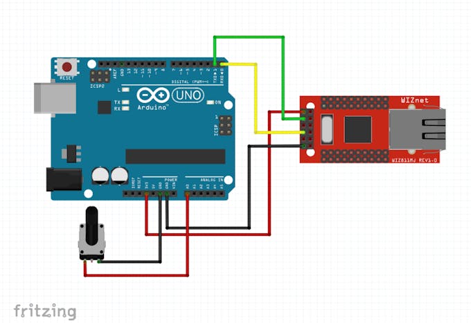
Since we’ve gotten the lock to work, we are now ready to setup the WIZ750SR, we can connect the WIZ750SR to Arduino UNO with relay like the image below. Arduino UNO only have Serial port that’s basically pin 0 and 1 for RX and TX
We can use following Arduino code to send rotary information to s2e.
#include <SoftwareSerial.h>
#define ROTARY_ANGLE_SENSOR A0
#define ADC_REF 5 //reference voltage of ADC is 5v.If the Vcc switch on the seeeduino                  //board switches to 3V3, the ADC_REF should be 3.3
#define GROVE_VCC 5 //VCC of the grove interface is normally 5v
#define FULL_ANGLE 300 //full value of the rotary angle is 300 degrees
int incomingByte = 0;   // for incoming serial data
float previous = 0;
char degreebuffer[20];
void setup() {
// initialize the LED pin as an output:
 Serial.begin(115200);     // opens serial port, sets data rate to 9600 bps
 pinMode(ROTARY_ANGLE_SENSOR, INPUT);
 //mySerial.begin(115200);
}
void loop() {
 float voltage;
 int sensor_value = analogRead(ROTARY_ANGLE_SENSOR);
 voltage = (float)sensor_value*ADC_REF/1023;
 float degrees = (voltage*FULL_ANGLE)/GROVE_VCC;
 //Serial.println("The angle between the mark and the starting position:");
 if(degrees != previous)
 {
   dtostrf(degrees, 0, 2, degreebuffer);
   Serial.write(degreebuffer);
   Serial.write('n');
 }
 previous = degrees;
 delay(100);
}
Step 5: Program Philips Hue
To program hue, we first need to find out the ip of the Philips Hue Hub by visiting
https://discovery.meethue.com/
Once we find our internal ip we can go to
http://<bridge ip address>/debug/clip.html
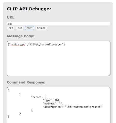
From here we can post to API and put message body type as
{"devicetype":"WIZNet_Controller#user"}
When we send message as a POST we should get a message like the link below, but that just means we have to click the link button to get the result
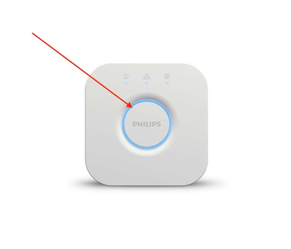
We need to click on the Link button below
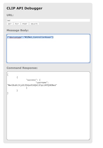
After clicking it we need to POST again to get our UserId
After that you can run the command
http://<bridge ip address>/api/{userid}/lights to get all the lights you need
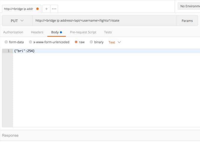
And for this example we will be using Hue Go. Use PUT method to test this out.
PUT http://<bridge ip address>/api/<username>/lights/1/state
{"bri":254}
We can try it on Postman
Once this works we can move onto next step
Step 6: Set Up Local Server on Your Computer
We can create server code on almost any computer, as both WIZ750SR and Hue is operating on local network. The code below should work to get the entire operation running.
var http = require('http');
var net = require('net');
var client = new net.Socket();
client.connect(5000, '192.168.1.81', function() {
 console.log('Connected');
});
client.on('data', function(data) {
 if(!String(data).includes(";") || String(data).length < 3)
 {
   return;
 }
 var nums = String(data).split(';');
 var num;
 if(nums.length >=2)
 {
   num = parseFloat(nums[nums.length-2]);
 }
 else if(nums.length == 1)
 {
  num = parseFloat(nums[0]);
 }
 var brightness = String(Math.floor(num/300*254));
 var options = {
   host: '<bridge ip address>',
   port: 80,
   path: 'api/<username>/lights/1/state',
   method: 'PUT'
 };
 var req = http.request(options, function(res) {
   console.log('STATUS: ' + res.statusCode);
   console.log('HEADERS: ' + JSON.stringify(res.headers));
   res.setEncoding('utf8');
   res.on('data', function (chunk) {
     console.log('BODY: ' + chunk);
   });
 });
 req.on('error', function(e) {
   console.log('problem with request: ' + e.message);
 });
 req.write('{"bri":' + brightness + '}');
 req.end();
 console.log('Received: ' + String(data));
 console.log('bri: ' + brightness);
});
client.on('close', function() {
 console.log('Connection closed');
});
Simply run this program in node and everything should work.

COMMENTS