Project board for Espruino Pico
Turn your Espruino Pico (Espruino.com – Javascript for Things) into a 4″ by 4″ protoboard playground!
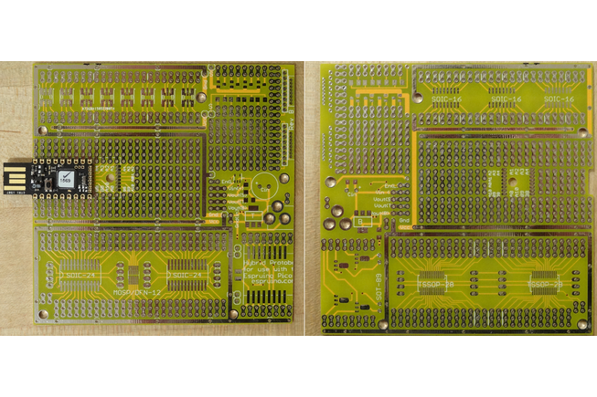
This board provides pads for the most popular surface-mount packages, broken out to rows of 0.1″ pin header for ease of connection. Each pin goes to two or three holes, so making multiple connections to a pin is no problem. At the top, a row of 8 pads that can take either an SOT-23-6 part (such as the MAX1555 LiPo charger IC, or some small EEPROMs), or the 5050 package commonly used for RGB-LEDs, including the WS2812/B. On the back of the board, these pins go to pads for three SOIC-16 packages (you can put two SOIC-8’s next to each other too). To the right of that are two banks of pads for SOT-23 MOSFETs. Each bank of 4 fets is connected to a common source, and pads are provided for a resistor between source and gate. A barrel jack, and optionally voltage regulators (in SOT-223 and SOIC-23-5 package) can be added to supply power.
The popular ESP8266 wifi module can be easily used with the pads in the lower right corner. These are for the Wi7-7 and Wi7-12 package (from Electrodragon and others), and pads are provided for a capacitor across the power supply, since these seem to need it (of course, you can use the Wi7C-1 with the 8 pins in the through-hole prototyping area). These pads have the same spacing as used in the HopeRF RF transceiver modules and many others. The spacing is also the same as used in 1W RGB/RGBW LEDs. While the LED would rapidly overheat at full power, this might be useful at a lower duty cycle, or for brief flashes. In this case, the SOT-89 pads on the underside can be used for AMC7135 current regulators for the LEDs.
All through-holes are plated.
Three ways to mount a Pico
- On castellated pads, with the USB connector hanging over the edge
- On pin header, with the USB connector hanging over the edge
- On pin header, using the second set of pins, with the USB connector flush with the edge of the board.
Features
- Row of 8 SOT-23-6/5050 pads on front, 3 SOIC16 pads on back
- Two sets of pads for 4 SOT-23 MOSFET w/pads for resistor between gate and source
- Two rows of 8 pins in 0.1″, 2mm, and 0.05″ pitch
- Set of 2 SOIC24W/N and one DFN-12 (or MSOP-12 0.65mm pitch) pads (great for TEOS light and color sensors) on front, 2 SSOP-28 and one MSOP-12 0.5mm pitch on back
- Multiple smaller SOIC or SSOP parts can be placed in one of the larger footprints.
- Four-wire signal bus runs the length of SOIC24/MSOP/SSOP area – ideal for working with multiple I2C or SPI devices
- Pads to mount a barrel power jack (center positive), input capacitors
- Pads for three voltage regulators in standard pinouts (two TO-223, one SOT-23-5) and caps
- Exposed GND and Vcc traces for easy power and ground wiring
- Pads for ESP-8266 (castellated pad version) + supply capacitor
- ESP-8266 pads can also be used for HopeRF products, or high power LEDs (with limited duty cycle)
- Pads for four SOT-89 devices, behind ESP8266
- Six mounting holes, five of which connect to ground
- Ample traditional through-hole prototyping space.

Example
This shows one of my projects using one of these boards, demonstrating the versatility of this prototyping board. Actual assembly of the hardware went very fast – it was almost negligible compared to the time spent writing the software. With all these devices, there’s still plenty of room left on the board – I could have added another ‘2812 LED, and several more IC’s in (T)SSOP, SOIC, or DIP.

On the top, you can see the Pico itself, a WIZNet Wiz550io module (keypad and cover are mounted to that), 4-button keypad, and a BMP180 temp+humidity sensor. A TCS34723 color sensor is mounted on the DFN pads in the middle, with an 0603 cap used for bypassing (barely visible in picture – they’re tiny!). The two LEDs are WS2812B leds, to control 6 status lights with 1 Espruino pin. The light is conveyed to the top of the cover using Sparkfun’s flexible light pipe.

On the bottom, you can see a prototype RF controller board (may be offered for sale in future) that offloads the task of listening to 433mhz RF to an external ATtiny841, and communicates with the Espruino over serial, as well as a TSSOP-8 AT24-series I2C EEPROM, and lots of wiring; the traces running down the middle at the bottom are I2C SDA and SCL. The two unoccupied headers are for an EasyVR 3.0 voice recognition board.
COMMENTS