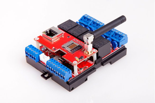
ProDino Zero GSM Ethernet
If you want a faster, modern and powerful Arduino board with Ethernet connection, a ProDino Zero GSM Ethernet V1 board is for you. You can use it for various applications, from home projects to industrial use. It also as a great educational tool for learning about 32-bit application development. The board is powered by Atmel’s SAMD21 MCU, which features a 32-bit ARM Cortex® M0+ core, SARAU201 GSM module W5500 Ethernet chip.

Communication
ProDino Zero GSM Ethernet V1 version is ideal for makers wanting to design IoT projects with minimal experience in networking. The board combines functionality of Zero and global GSM connectivity and is based on the Atmel SAMD21 and SARAU201 GSM module supply global coverage HSPA/GSM. Thanks W5500 Ethernet chip allows you to have a wired Ethernet connection between your board and Internet. This allow you to have simultaneously two different communication channels. Through Ethernet and GSM. The ProDino Zero GSM Ethernet V1 has 4 relays. The 4 Relays are a solution for driving high power loads that cannot be controlled by the microcontroller’s digital IOs, due to the current and voltage limits of the controller. Each relay provides 2 pole changeover contacts (NO and NC). Relays are useful in switching on/off AC appliances like fan, light, motor or high current DC actuators like solenoid valve etc. Included four LEDs to indicate the on/off state of each relay. The 4 digital inputs are isolated. This is helpful for connecting ProDino Zero GSM Ethernet V1 to a system with a different ground and different voltage or noisy system. This electrically isolates a controller from the high-power system by use of an opto-isolator IC. This allows the low-voltage side to control a high voltage side. Great for use in noisy circuits where signal lines require electrical isolation. Four LEDs indicate the On/Off state of each input. The ProDino Zero GSM Ethernet V1 board contains one GROVE Digital connector. The Grove System simplifies traditional electronics it consists of a base platform and various modules with standardized connectors. Each Grove module addresses a range of functions such as simple LEDs, buttons, switches to complex servo control, etc. With the combination with Grove modules, the project possibilities are endless! Thanks that the ProDino Zero GSM Ethernet board owns RS485, now you will be able to have a communication port for your RS485 devices! It will allow up to 32 devices to communicate through the same data line over a cable length of up to 1200m/4000ft. It is the ultimate expansion that allows your board to connect to almost every legacy industrial system using serial connectivity such as industrial PLCs, controllers, drives and HMIs. The RS485 can be use to turn old industrial systems like industrial machinery, heating systems and conveyors into new IoT devices. It supports high speed 500 Kbps in a short distance. The ProDino Zero GSM Ethernet contains more a micro USB connector and a reset button. It is compatible with “Arduino MKR GSM 1400”.
Getting started
You can find in the Tutorial section all the information you need to configure your board, use the Arduino Software (IDE), and start tinkering with coding and electronics. What you can do with this board see our Examples.
Features
- ATSAMD21G18 Microprocessor, 32-Bit ARM Cortex® M0+
- SARAU201 GSM module
- W5500 Ethernet chip
- 1 x GROVE connector
- 4 Relays Output
- Pluggable connectors
- 4 Optical Isolated Inputs
- RS485 port
- Switching Regulators power supply
- Arduino MKR GSM1400 compatible
Specification
- mP, DC Current per I/O Pin 7 mA
- Clock speed 48 MHz
- SRAM 32 KB
- 256 KB Flash Memory
- GSM global regions UMTS/HSPA: 800 / 850 / 900 / 1900 / 2100 Mhz
- Ethernet 802.3 10/100 Mbit/s
- RS485 speed 500 Kbps (short distance)
- Optical isolated digital Inputs: 4 (working voltage 3-30 V, On arrives form 3 V)
- Relay outputs: 4 (maximum voltage/current 250V/5A)
- Input Voltage: (Vin) 8 – 30 V
- Dimension: 70 mm X 92 mm X 32 mm
- Weight: 152 g
Additional connectors
GROVE

J10 Grove Digital (External)
- 1 GROVE_D0 – Primary digital Input/Output D12_I2C_SCL
- 2 GROVE_D1 – Primary digital Input/Output D11_I2C_SDA
- 3 Vcc – Grove module powers 3,3 V
- 4 GND – Ground
What does the board consume?
| Voltage | All relays off | All relays on |
|---|---|---|
| 8 V | 0.080 A | 0.260 A |
| 12 V | 0.050 A | 0.170 A |
| 24 V | 0.030 A | 0.100 A |
COMMENTS