Step 1: Soldering Resistors and Wire to the Tri-color LED
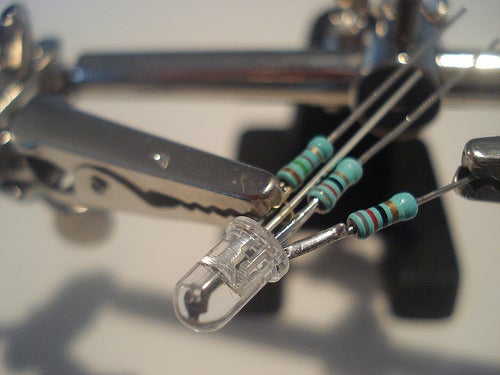
- Shorten all except for the longest leg of the LED
- Solder the resistors to the LED legs as shown below
- Shorten the remaining long leg
- If you use the Adafruit LED, solder the red wire to it [as shown below]
- If you use the SparkFun LED, solder the black wire to it
Step 2: Connecting the LED to the Ethernet Shield
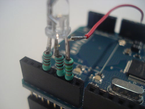
- Stack the Ethernet shield onto the Arduino
- Connect the LED to the pins 3, 5 and 6 (red) of the Ethernet shield
- If you use the Adafruit LED, connect the red wire with the 5V pin of the Ethernet shield
- If you use the SparkFun LED, connect the black wire with the GND pin of the Ethernet shield
Step 3: Uploading the Arduino LED Test
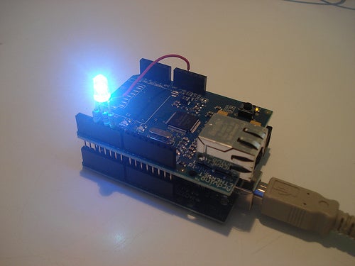
To test the LED you can upload the following sketch to your Arduino. Reset the Arduino and make sure the colors show up in the exact same sequence as described in the code comments of the loop statement below. If you use the SparkFun LED uncomment the corresponding lines of code and delete the three analogWrites of the Adafruit LED. If the colors show up in another sequence you might have swapped some pins.
// HelloLed.pde
int redPin = 6;
int greenPin = 5;
int bluePin = 3;
void setColor (int red, int green, int blue) {
// SparkFun LED: write value for each color
//analogWrite(redPin, red);
//analogWrite(greenPin, green);
//analogWrite(bluePin, blue);
// Adafruit LED: write inverted value for each color
analogWrite(redPin, 255 – red);
analogWrite(greenPin, 255 – green);
analogWrite(bluePin, 255 – blue);
delay(1000);
}
void setup () {
pinMode(redPin, OUTPUT);
pinMode(greenPin, OUTPUT);
pinMode(bluePin, OUTPUT);
}
void loop () {
setColor(0, 0, 0); // Off
setColor(255, 0, 0); // Red
setColor(0, 255, 0); // Green
setColor(0, 0, 255); // Blue
setColor(0, 255, 255); // Aqua
setColor(255, 255, 0); // Yellow
setColor(255, 0, 255); // Fuchsia
setColor(255, 255, 255); // White
}
Step 4: Editing and Uploading the Arduino LED Web Service
Once you made sure the LED works, you’re ready to edit and upload the sketch for the LED Web service to your Arduino.
First, install the YalerEthernetServer.zip Arduino library (for details please see https://yaler.net/arduino) then download the YalerLedWebService.inosketch and open it in your Arduino IDE.
Then you have to carry over the changes made to setColor in the previous step. If you did change the pin numbers, carry those changes over as well.
You also have to set the MAC address of your Ethernet shield. It is possible to use the value from the source code, but be aware that address conflicts might arise if a device in your LAN is already using this same address. The MAC address is set in the line byte mac[] = { 0xDE, 0xAD, 0xBE, 0xEF, 0xFE, 0xED }; and most of the time it is sufficient to change the last byte to another value, e.g. 0xAA.
The next step is to set your Yaler relay domain. You can get a free trial account at https://yaler.net/.
(If you run your own Yaler relay server instance, you’ll also have to enter the appropriate host name.)
So, all that’s left is to upload the sketch and connect your Arduino to the Internet with an RJ45 cable. In order for the service to run, the LAN must provide DHCP. It’s possible to use a fixed IP, but this requires a few changes to the source code that go beyond the focus of this tutorial. To make sure there are no start up timing issues with the Ethernet shield, press the reset button once the Arduino is connected to the LAN.
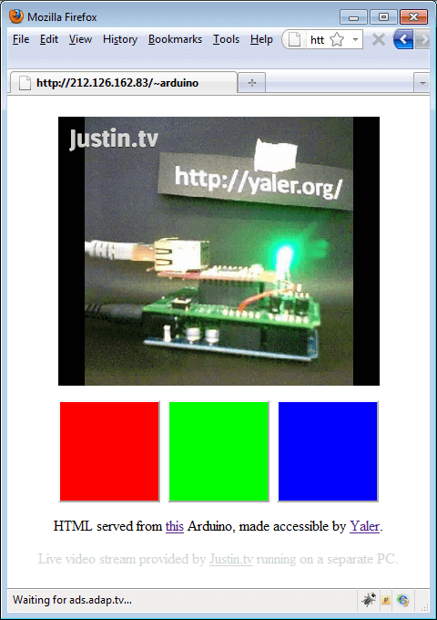
Step 5: Accessing and Controlling the Arduino From the Web
If the Arduino is connected to the LAN and thereby to the Internet, and if the Yaler instance at the specified IP address is up and running, you should now be able to access the Arduino Web LED at http://{Yaler IP}/{Relay Domain}/led, e.g. http://gsiot-ffmq-ttd5.try.yaler.io/
You’ll get an HTTP 504 Gateway Timeout if the Arduino is not running . Depending on your browser this is shown as a blank page or as “Gateway Timeout”. In this case, make sure everything is tightly plugged in and try resetting the Arduino.
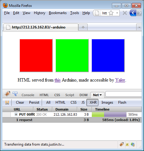
If everything works as intended, you should see a simple HTML page with three colored buttons . If you press a button, the Arduino LED should light up in the corresponding color.
Behind the scenes this works with a simple Javascript that sends an HTTP PUT request , e.g. PUT http://gsiot-ffmq-ttd5.try.yaler.io/led/ff0000 to the Arduino to set the LED’s color. You can use Firefox with the Firebug add-on set to Net > XHR to see the PUT requests.
Note that the URL does not depend on the current location of the Arduino. No matter if it’s attached to your home network or to the LAN at your office, the URL remains the same. Just plug in the Arduino and control it with your browser.
Because typing the URL can be cumbersome, you can make use of a QR-Code generator like http://qrcode.kaywa.com/ to get a QR-Code of your Arduino’s URL (example below).
Print it, stick it to your Arduino, access it with a QR-Code reader like Lynkee (iPhone), Kaywa (Symbian, Java phones) or Quickmark (Windows Mobile) and there you have a switch-less, yet conveniently controllable Arduino.
COMMENTS