There are cases where we cannot totally rely on WiFi network for internet connectivity with device, thus we will prefer to use wired connection in such cases, network critical applications must be provided with wireless and wired connectivity options in order to achieve greater result and to get more flexibility and reliability and this can be accomplished by integrating the Ethernet protocol, which is the basic of the communication protocol used in the internet into the embedded system. There are lots of options available in the market to get the Ethernet connectivity and one of the option to get Ethernet connectivity to your own micro controllers is by adding WIZ811MJ Ethernet module to your microcontrollers.
Introduction to WIZ811MJ Ethernet module
The module we are going to use in this hookup is WIZnet W5100 Network Module with Mag Jack – WIZ811MJ. The WIZ811MJ is an ideal option for users who want a simple solution to adding TCP/IP and rapidly enabling Internet capability to their project. The WIZ811MJ network module comes with the Wiznet W5100 chip, MAG-JACK (RJ45) together with the glued logic needed to communicate with the microcontroller through the SPI or bus interface.
WIZ811MJ consists of W5100 and MAG-JACK.
- TCP/IP, MAC protocol layer: W5100
- Physical layer: Included in W5100
- Connector: MAG-JACK(RJ45 with Transformer)
We are using the version 1.1 of the WIZ811MJ module, its comes with following features:
- Supports 10/100 Base TX
- Supports half/full duplex operation
- Supports auto-negotiation and auto cross-over detection
- IEEE 802.3/802.3u Compliance
- Operates 3.3V with 5V I/O signal tolerance
- Supports network status indicator LEDs
- Includes Hardware Internet protocols: TCP, IP Ver.4, UDP, ICMP, ARP, PPPoE, IGMP
- Includes Hardware Ethernet protocols: DLC, MAC
- Supports 4 independent connections simultaneously
- Supports MCU bus Interface and SPI Interface
- Supports Direct/Indirect mode bus access
- Supports Socket API for easy application programming
- Interfaces with two 2.54mm pitch 2 x 10 header pin
- Temperature : 0 ~ 70℃ (Operation), -40 ~ 85℃ (Storage)


The Wiznet 5100 based chip has the TCP/IP hardwired on it; therefore it will help developing the TCP/IP protocol stack based application much easier and could be implemented on the small RAM size microcontroller class compared to the firmware TCP/IP protocols stack based implementation approach.

We are going to use this module together with arduino to get started with it. The Arduino UNO does not have any options onboard to connect with internet, adding this module to Arduino UNO will give the Ethernet connectivity to the UNO board, thus it will provide a great option to create internet dependent applications using Arduino UNO board. You are free to use Arduino ethernet shield also (Since the ethernet sheild comes with same W5100 Chip onboard).
The Arduino can produce web pages from within the Arduino sketch or host web pages that are stored on the SD card (there is a micro SD card socket on the Arduino Ethernet shield). These web pages can be configured to control and monitor hardware from a web browser on any Ethernet network that the Arduino is connected to. The WIZ811MJ module uses SPI Protocol to communicate with other devices, thus we are going to connect the Ethernet module to the arduino using SPI lines.
Note that MISO, MOSI, and SCK are available in a consistent physical location on the ICSP header; this is useful, for example, in designing a shield that works on every board.

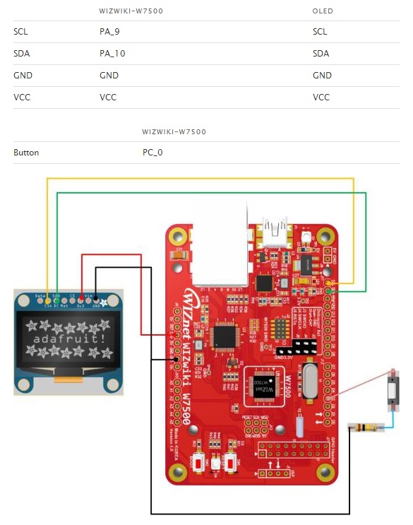
Connections
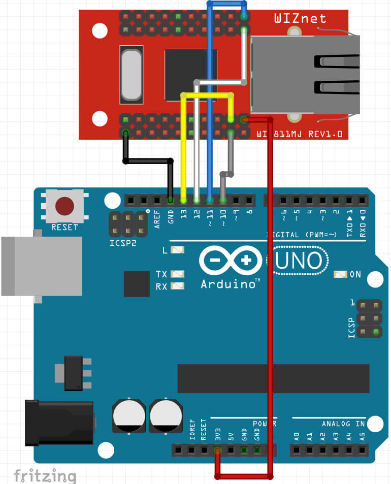
The connections between the Ethernet module and Arduino is really simple, you just need six lines to be connected to get it going. Refer the Images below to connect your circuit.


Circuit generated Using Fritzing Software

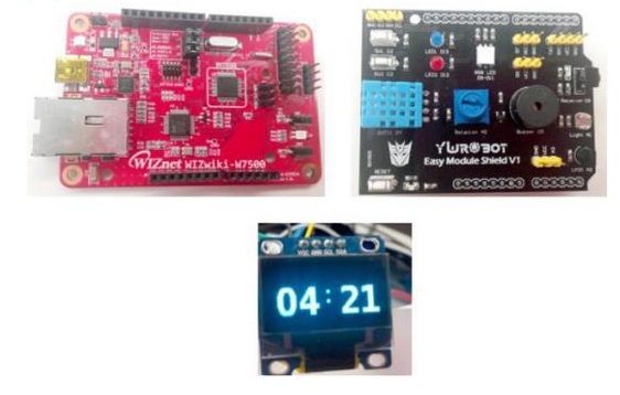
Connect the Jumper wires as mentioned above, once done power up your arduino and connect the Ethernet cable from the router to the WIZ811MJ Module. Refer the next section to see the code used for this module.
Sample Code
We have reached the last step of this hookup guide, only thing left in this hookup guide is to upload the code to the arduino and see the output. In order to get it running we are going to use the Arduino Ethernet Library which comes by default when you install the software.
Open the example code from this mentioned path:
Arduino Examples -> Ethernet -> WebServer
or copy paste the follwing into your arduino and upload the code
/*
Web Server
A simple web server that shows the value of the analog input pins.
using an Arduino Wiznet Ethernet shield.
Circuit:
* Ethernet shield attached to pins 10, 11, 12, 13
* Analog inputs attached to pins A0 through A5 (optional)
created 18 Dec 2009
by David A. Mellis
modified 9 Apr 2012
by Tom Igoe
*/
#include <SPI.h>
#include <Ethernet.h>
// Enter a MAC address and IP address for your controller below.
// The IP address will be dependent on your local network:
byte mac[] = {
0xDE, 0xAD, 0xBE, 0xEF, 0xFE, 0xED
};
IPAddress ip(192, 168, 1, 177);
// Initialize the Ethernet server library
// with the IP address and port you want to use
// (port 80 is default for HTTP):
EthernetServer server(80);
void setup() {
// Open serial communications and wait for port to open:
Serial.begin(9600);
while (!Serial) {
; // wait for serial port to connect. Needed for Leonardo only
}
// start the Ethernet connection and the server:
Ethernet.begin(mac, ip);
server.begin();
Serial.print(“server is at “);
Serial.println(Ethernet.localIP());
}
void loop() {
// listen for incoming clients
EthernetClient client = server.available();
if (client) {
Serial.println(“new client”);
// an http request ends with a blank line
boolean currentLineIsBlank = true;
while (client.connected()) {
if (client.available()) {
char c = client.read();
Serial.write(c);
// if you’ve gotten to the end of the line (received a newline
// character) and the line is blank, the http request has ended,
// so you can send a reply
if (c == ‘\n’ && currentLineIsBlank) {
// send a standard http response header
client.println(“HTTP/1.1 200 OK”);
client.println(“Content-Type: text/html”);
client.println(“Connection: close”); // the connection will be closed after completion of the response
client.println(“Refresh: 5”); // refresh the page automatically every 5 sec
client.println();
client.println(“<!DOCTYPE HTML>”);
client.println(“<html>”);
// output the value of each analog input pin
for (int analogChannel = 0; analogChannel < 6; analogChannel++) {
int sensorReading = analogRead(analogChannel);
client.print(“analog input “);
client.print(analogChannel);
client.print(” is “);
client.print(sensorReading);
client.println(“<br />”);
}
client.println(“</html>”);
break;
}
if (c == ‘\n’) {
// you’re starting a new line
currentLineIsBlank = true;
}
else if (c != ‘\r’) {
// you’ve gotten a character on the current line
currentLineIsBlank = false;
}
}
}
// give the web browser time to receive the data
delay(1);
// close the connection:
client.stop();
Serial.println(“client disconnected”);
}
}
Once done with uploading the code, you must open the serial terminal. Now open web browser in your Computer and copy paste this IP address 192.168.1.177 to your address bar and hit enter. If some page loads up showing up values from the arduino it means your connection is established successfully. In order to see the sensor readings on the web page, connect some sensors or potentiometer to Analog pins A0, A1, A2, A3, A4 and A5. You are able to read these values on the web page. Now try with other examples provided with Ethernet library.
COMMENTS