New, three dimensional desktop printer control system based on STM32F4 microcontroller with extended interfaces

The article presents the design of a new three-dimensional desktop printer control system developed with use of experience in the operation of equipment for the mass market.
introduction
The article presents the design of a new three-dimensional desktop printer control system developed with use of experience in the operation of equipment for the mass market. Paper introduces in printing technology basis and outlines its historical context. Solutions to improve operational stability and functionality compared to the original design are proposed. New design bases on the achievements in the domain of open source software. Control over the printing process through the use of feedback signals to enable detection of movement errors is increased. With support for up to seven parallel stepper motor drives, it became possible to use multi-coloured head with up to four colours. The new design and dedicated embedded program for control system based on a modern and efficient STM32F4microprocessor family gives a substantial contribution to the development of a new branch of the three-dimensional printing. The article describes a first known attempt to use 32-bitSTM32F4 unit with popular open-source project called Marlin and Teacup for 3D printer. Multiple communication interfaces support integration with industrial automation at IT and process-automation level. Descriptions of the functional implementation are verified by laboratory tests.
features
The idea of the spatial (three-dimensional) printing, understood as the process of creating real objects of arbitrary shape based on a computer model is not new. The technology was developed already in 1980 leading to the establishment of the first operating structure in 1984 by 3D Systems company [1]. There are several methods of 3D printing. The more popular include: FDM- Fused Deposition Modelling and DMLS - Direct Metal Laser Sintering. Suitable examples of the FDM and DMLS printing are presented in Figure 1. The first method (FDM) based on the extraction of plasticized material by following the head by path coordinated with extrusion process. A layer-bilayer, reference model geometry of the spatial object is created. 
technical details
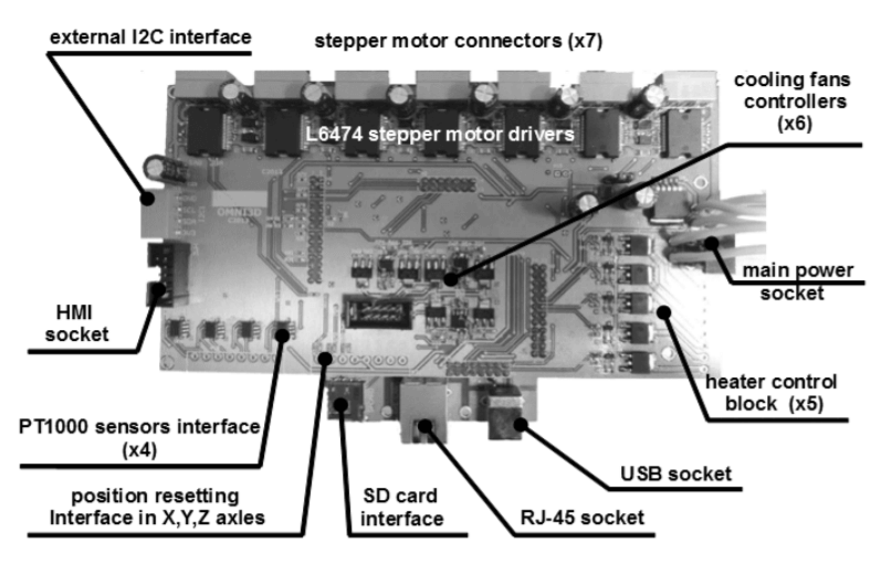
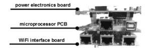
The main goal of the new project is elimination of limitations pointed out in previous chapter by:  use of much more efficient microcontroller family STM32F4 [11] with maximum computing power at 210 [MIPS] and hardware floating point operations support,  use of L6474 drivers with lower output stage transistors conduction resistance RDS(On) (180/370 [mΩ] with 320/320 [mΩ] in the driver A4988 in low/high side of the output bridge), lower thermal resistance (32 [K/W] reduced to 12 [K/W]), a higher value of effective continuous phase current (3[A] vs 2[A] in reference design),  use of SPI digital interface with motor drivers with remote configurable current amplitude and availability of the feedback signal from the detected errors [12],  use of temperature sensors based on PT1000-behaved linear response R(T) dependence and higher accuracy using an appropriate analog conversion path, storage interface implementation based on the SDIO (native interface of SD cards),  implementation of the built-in Full Speed (FS) USB interface using the CDC device class operating directly with build in MS Windows driver (12 [Mbps] vs 1[Mbps] with FDI chip usage),  implementation of the Ethernet/WiFi interface as an novel alternative for USB in desktop printers. As shown on Figure 5, the controller consists of three separable PCBs (Printed Circuit Boards):  power electronics,  microprocessor,  wireless communication - WiFi board (optional). For wireless communication a WizFi630 module is used. This module is chosen because of the user interface IEE802.11b/g/n providing full bus bandwidth and the ability to communicate via wired Ethernet.
how to use

Screenshot 2021-03-02 115354.png

The very important aspect of the new design is to introduce Ethernet interface as an alternative to the USB. The USB interface at FS (full speed) mode uses standard STM32F4 peripheral. Embedded system driver is developed to comply with CDC device class [13]. Furthermore, after considering the Windows system requirements [14] it is possible to use standard USB driver with no additional installation requirement. An Ethernet interface uses Ethernet STM32F4 peripheral and DP83848 MAC driver with reference design [15]. Wi-Fi communication uses wired Ethernet channel of WizFi360 module [16]. As the Wi-Fi module is transparent to the system there is nothing more to discuss. To make the Ethernet interface usable and compatible with Pontefract (printer PC host), software needs to be recompiled in Windows environment (it is possible using the instruction from [17] web page, installing the py2exe extension and use of the supported compilation script setup.py file). Nowadays, native Python 2.7 IDE could be setup on Visual Studio. The Windows compilation of the newest Pontefract version is necessary because of the TCP Stream option availability from configuration menu. TCP Stream needs to be off while using Ethernet connection in the synchronous mode comparable to the USB (COM emulation) interface. Figure 7 presents Pontefract compiled under Windows from source binaries (Python language).

documents
Code
Research Paper

COMMENTS

Please Login to comment
  Subscribe  
Notify of