1. Preparation
Hardware preparation
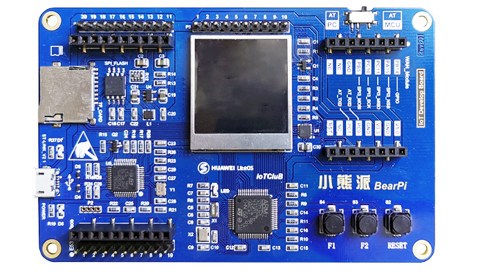
- Development board
First, you need to prepare a development board, here I am preparing the STM32L4 development board (BearPi):
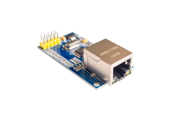
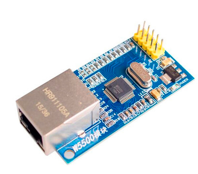
- W5500 Ethernet module
Here I use the common Ethernet module W5500:
Software preparation
- Need to install Keil-MDK and the corresponding package of the chip in order to compile and download the generated code;
- Prepare a serial port debugging assistant, here I am using
Serial Port Utility; - Prepare a network debugging assistant, here I am using
sockettool;
2. Generate MDK project
Select chip model
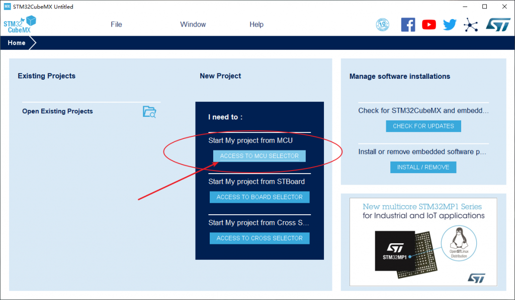
Open STM32CubeMX, open the MCU selector:
STM32L431RCT6: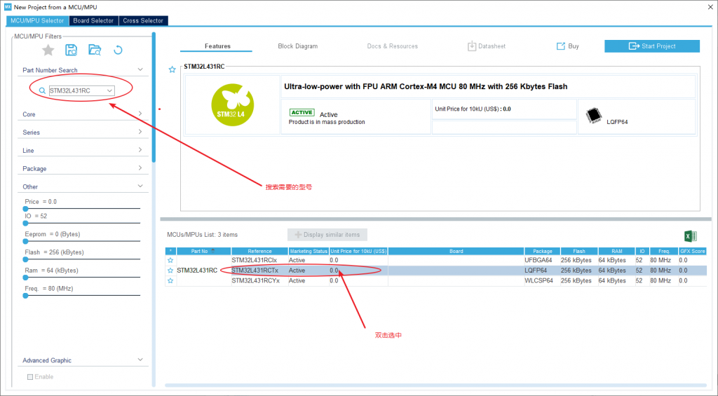
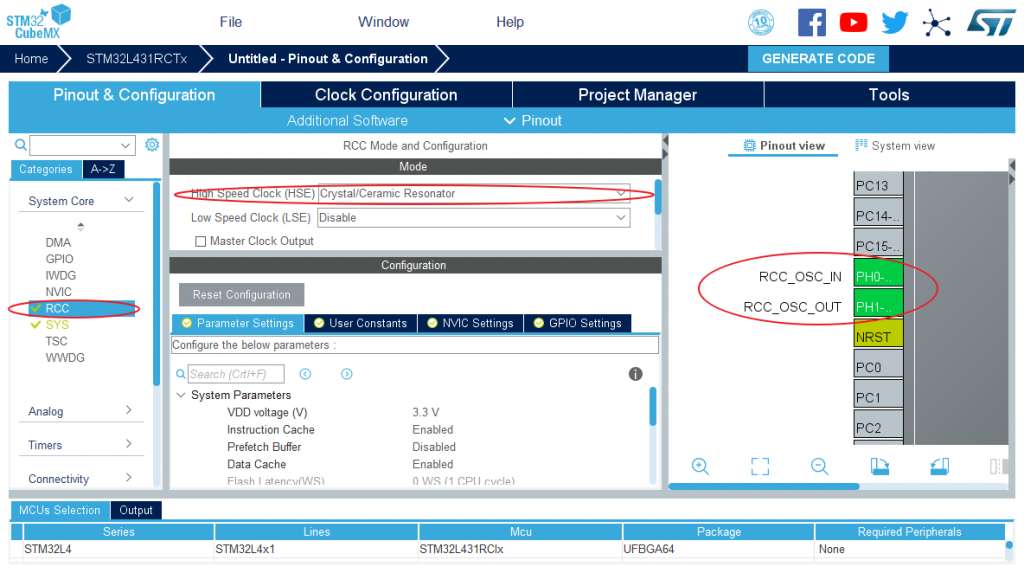
- If you choose to use an external high-speed clock (HSE), you need to configure RCC in System Core;
- If the default internal clock (HSI) is used, this step can be skipped;
Here I use an external clock:
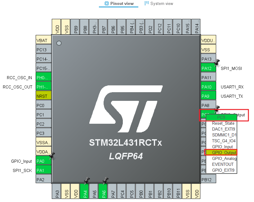
Configure Ethernet module to control GPIO
There are two GPIOs that need additional configuration for the Ethernet module:
| Ethernet module pin name | GPIO | effect |
|---|---|---|
| RST | PC9 | Ethernet module hard reset |
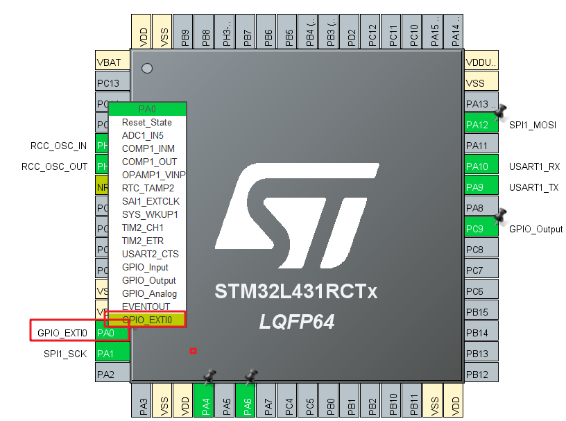
| INT | PA0 | Interrupt pin |
The reset pin can be configured as output mode:
The interrupt pin needs to receive the interrupt from the Ethernet module, so the EXTI external interrupt pin needs to be configured:
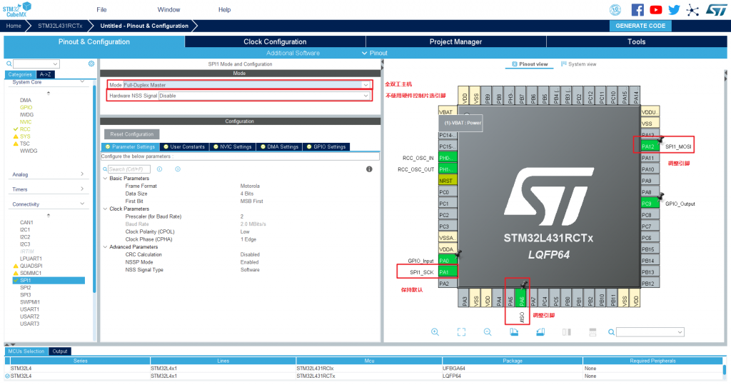
Configure SPI1 interface
In this experiment, I connected the Ethernet module to the SPI1 interface, and the pin correspondence table is as follows:
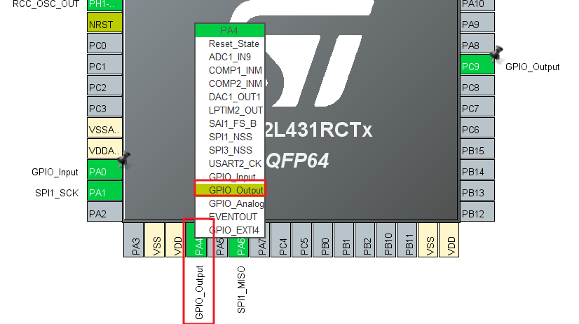
It should be noted that the SPI chip select pins are not controlled by hardware SPI peripherals, but are configured as ordinary GPIOs and controlled manually .
| Ethernet module pins | MCU pin |
|---|---|
| MISO | PA6(SPI1_MISO) |
| MOSI | PA12(SPI1_MOSI) |
| SCS | PA4(SPI1_NSS) |
| SCLK | PA1(SPI1_SCK) |
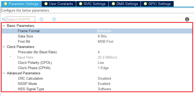
There are three points to note when configuring the SPI interface:
① Frequency division coefficient;
② CPOL: When the CLK is idle, the level is high or low;
③ CPHA: Sampling on the first clock edge or sampling on the second clock edge;
Next, start to configure the SPI1 peripheral. First, configure the mode and pins of the SPI1 peripheral:
Because you chose not to use the hardware SPI peripheral to control the chip select pin, you need to manually configure the chip select pin PA4:
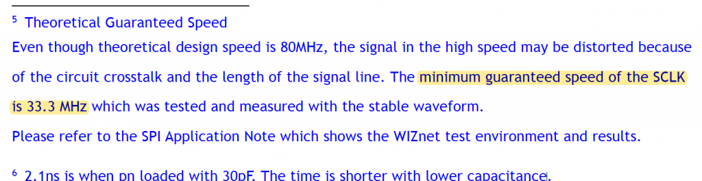
The SPI bus clock given in the W5500 manual is 80Mhz:
| Symbol | Description | Min | Max | Units |
|---|---|---|---|---|
| Fsck | SCLK Clock Frequency | – | 80 | MHz |
| TWH | SCLK High duration | 6 | – | ns |
| TWL | SCLK Low duration | 6 | – | ns |
| TCS | nSCS High duration | 5 | – | ns |
However, it should be noted that the manual clearly indicates that the actual guarantee is at least 33.3Mhz, so for the sake of safety, the SPI bus clock is configured as 20Mhz in this experiment :
For CPOL, W5500 supports both modes. Select the LOW mode when idle. The first clock edge is given in the CPHA manual:

In summary, the timing parameters are configured as follows:
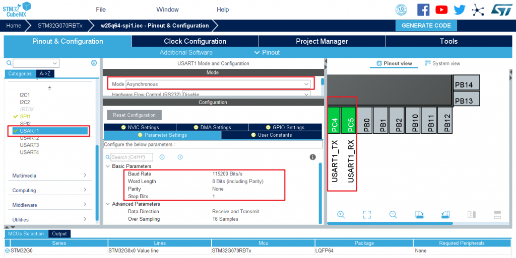
Configure the serial port
The development board has a CH340z for serial port, which is connected to USART1.
Next, start the configuration USART1:
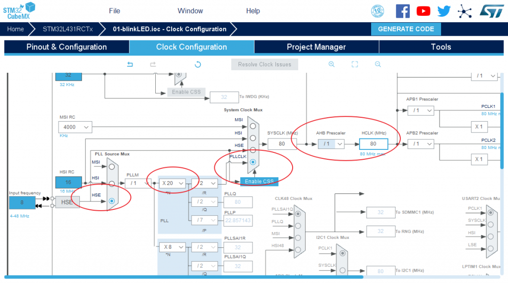
Configure the clock tree
The highest frequency of STM32L4 is 80M, so configure PLL, and finally use HCLK = 80Mhz:
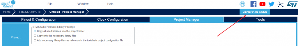
Generate project settings
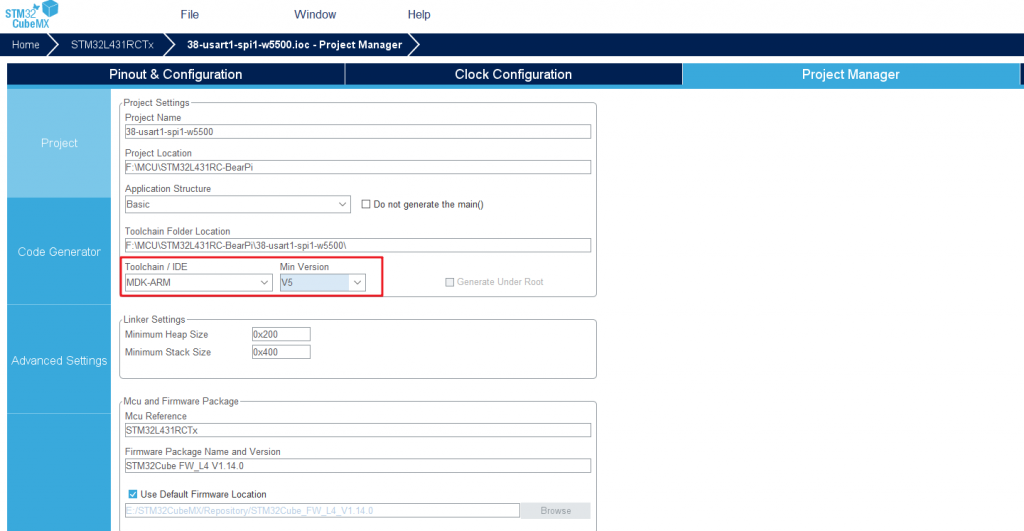
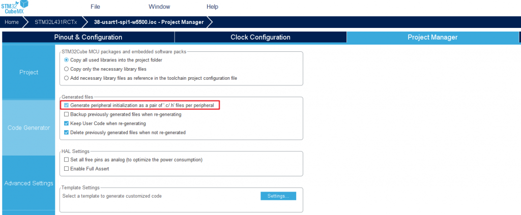
Code generation settings
Finally set to generate a separate initialization file:
Generate code
Click GENERATE CODEto generate MDK-V5 project:
3. Redirect printf function to USART1
Reference: [STM32Cube_09] Multiple methods to redirect printf function to serial port output .
4. Porting W5500 official driver library
4.1. Download the official driver library
W5500 officially provides ioLibrary v2.0.0. ioLibrary is the Ethernet driver library of the WIZnet chip, which includes drivers and application protocols. This driver (ioLibrary) can be used for the application design of WIZnet TCP/IP chips, such as W5500, W5300, W5200, W5100, W5100S.
There are two download addresses:
- github open source warehouse address: https://github.com/Wiznet/ioLibrary_Driver
- gitee warehouse address (for faster download speed, the blogger synced to gitee): https://gitee.com/mculover666/ioLibrary_Driver
The source code directory structure is shown in the figure:
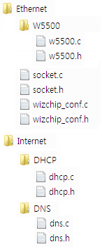
- Ethernet: SOCKET API interface similar to BSD, and WIZCHIP (W5500 / W5300 / W5200 / W5100 / W5100S) driver
- Internet: Various application layer protocol stacks
- DHCP client
- DNS client
- FTP client
- FTP server
- SNMP agent/trap
- SNTP client
- TFTP client
- HTTP server
- MQTT Client
4.2. Add the driver library to the project
Create a new Hardware/W5500 under the project directory and copy all three folders in the driver library:
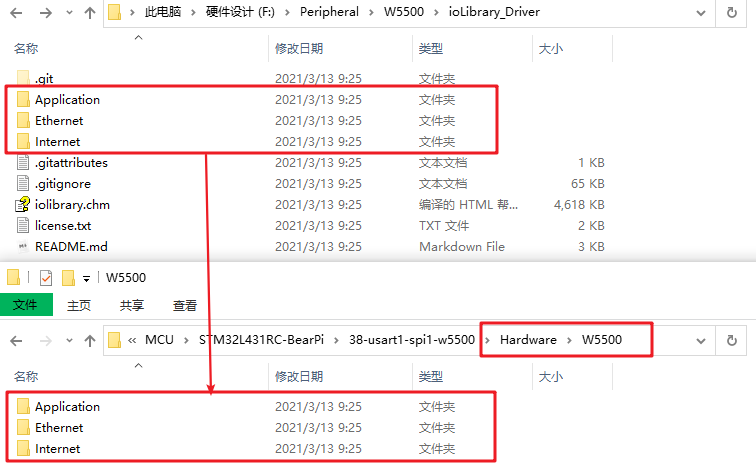
Note that only the files under Ethernet are required, and the files in the other two folders can be added optionally, which will be used in the test later.
Next, add files related to W5500 in the Ethernet directory to the MDK project:
COMMENTS