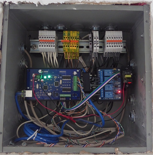
In my home automation project almost everything comes down to taking inputs and switching relays, so my first 8 I/O board based on an Arduino Nano and W5100 Ethernet module is deployed all over my house taking inputs from switches, buttons, contacts and providing outputs to control relays, etc. using MQTT. They have been very reliable (I can’t ever recall a crash) however the Nano started to become limiting. With only 2K of RAM (half of which used for libraries) and 16 usable I/O (without multiplexing, etc.) I have run out of space as I started to want to hang sensors off of it. Additionally without program space, OTA was out of the question.
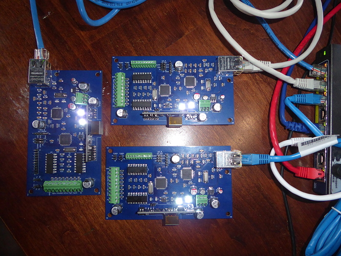
I wanted an SMD project, so I designed these new boards based on the Atmega 1284 and Wiznet W5100 Ethernet controller.
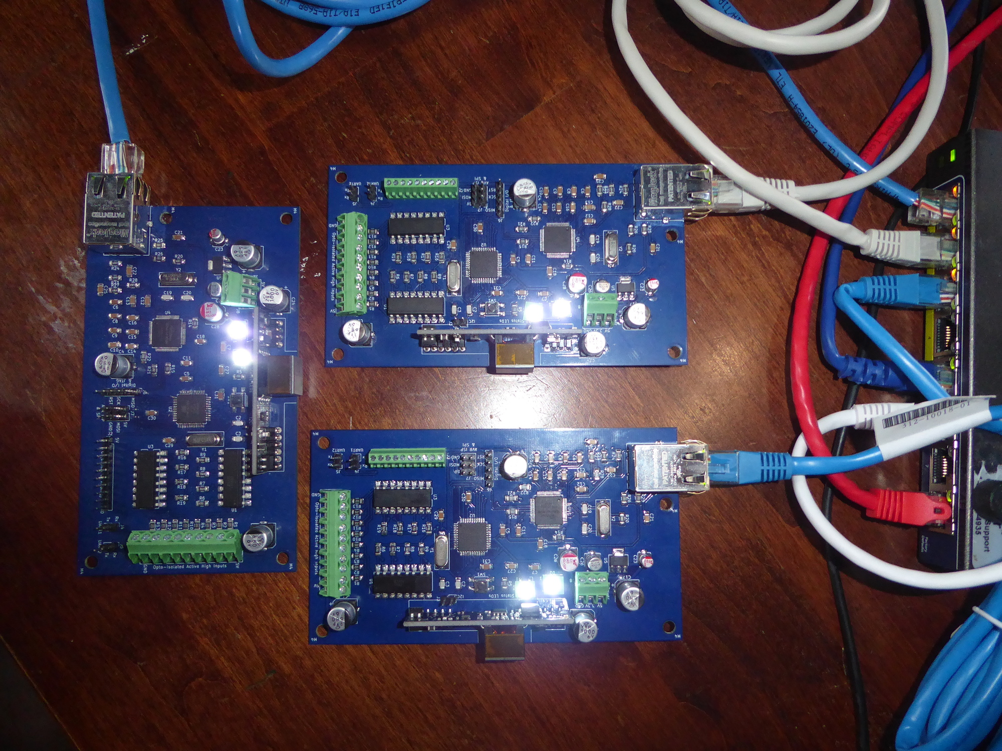
The specs are:
- Atmega 1284 w/128KB flash, 16KB RAM, 4K EEPROM, 16MHz
- Wiznet W5100 10/100 Ethernet
- 8 Opto-Isolated active high digital inputs on PD4-PD7, PC6/7, PB 0/1 (big terminal block)
- PA0-7 broken out for analog input and digital/analog output (small terminal block)
- SPI, I2C, 2xUART broken out to headers
- 6 remaining “spare” digital I/O broken out to header
- 2 x WS2812B LEDs for status and general fun
- Silvertel AG9700 PoE module
- 3 pin terminal for power supply or power source: 5V, 3V, ground
- Lots of filter capacitors, like an excessive amount
The leftmost board is my first prototype which I soldered manually with too large a soldering iron. Once I got to the Ethernet section I started using hot air soldering and continued for the rest of the boards. The layout of the boards could be more compact however with this being my first real SMD project I wanted it to be as easy as possible.
Software wise, I don’t have the code in a state worth posting (but I will if asked). Using PubSubClient for MQTT communication with Home Assistant. Nearly everything in my house is MQTT based as I have standardized upon it as the preferred protocol. The board pulls an IP address via DHCP, connects to the MQTT broker then just sends a topic on an input, or responds to a topic by changing outputs.
The software is mostly input agnostic. Can handle buttons, switches and contacts with input state detection as well as long/short press detection. An MQTT topic is sent when an input changes indicating state and another when the state changes again within a configurable timeout, providing the length of change.
My goal is to continue to expand the software to support a standard set of sensors and functions such as DHT, BMP280, RFID (UART), ec. sensors which are then activated by MQTT topics as required if the sensors are plugged into the board. I’m using the ArduinoOTA library to provide OTA firmware updates as these boards are often installed in inconvenient locations.
You may have noticed a mistake I made with the board layout. I accidentally stuck a capacitor in front of the power terminals. Oops. I also forgot the pullup resistor on the CS line so I have to make sure to manually pull it up the first time loading firmware, or load the firmware before soldering on the W5100.
COMMENTS