
Introduction:
First goes the list of the components I used:
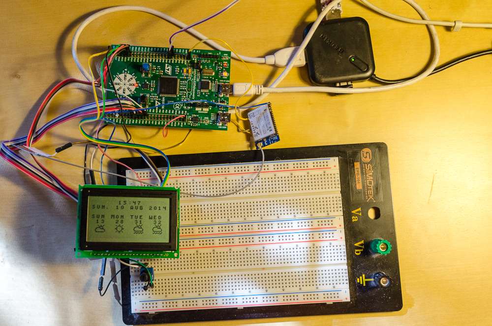
- Debug board STM32F3DISCOVERY.
- KS0108 controller based screen (in my case, it is Russian MT-12864A).
- WizFi220 Wi-Fi module.
Firmware may be developed at least in two IDEs: Keil Embedded Development Tools for ARM and IAR Embedded Workbench. I use the first one, but if you are interested in the other one, you will need IAR Embedded Workbench for ARM due to peculiarities of IAR.
Naturally, you should not forget about free means of development under ARM, e.g. the bundle Eclipse + GNU ARM Eclipse Plug-In + GCC + GDB + OpenOCD. Manuals on adjustment of this bundle may easily be found in the web.
Now then, why exactly STM? Because they have such a wonderful thing as Standard Peripherals Library (for STM32F303XX download here). It is a library which enables working with periphery, without touching registries. Here is an example of USART1 setting.
1 2 3 4 5 6 7 8 9 | USART_InitTypeDef USART_InitStructure; USART_InitStructure.USART_BaudRate = 115200; USART_InitStructure.USART_WordLength = USART_WordLength_8b; USART_InitStructure.USART_StopBits = USART_StopBits_1; USART_InitStructure.USART_Parity = USART_Parity_No; USART_InitStructure.USART_HardwareFlowControl = USART_HardwareFlowControl_None; USART_InitStructure.USART_Mode = USART_Mode_Rx | USART_Mode_Tx; USART_Init(USART1, &USART_InitStructure); |
Everything’s simple and clear, isn’t it? You should not surf Reference Manual (with STM32F303XX it takes nearly thousand pages). It is obvious that guys from STMicroelectronics did a great job.
However, use of this library is a holy war occasion (some say it generates a lot of unnecessary code, others — that is makes lazybones out of a programmer, etc.), therefore, I won’t encourage you, my reader, to use it. Just do as you see fit.
It is very easy to start development using this library due to two reasons:
- It already contains projects suitable for opening in IDE (for Keil, it is in Projects/STM32F30x_StdPeriph_Templates/MDK-ARM/Project.uvproj).
- The initial code for work with periphery can be added to the project by substitution of all files from Template to files of the sample you need.
So what is the role of controller in our task?
- Initializing and adjusting Wi-Fi and display.
- Requesting weather from OpenWeatherMap.
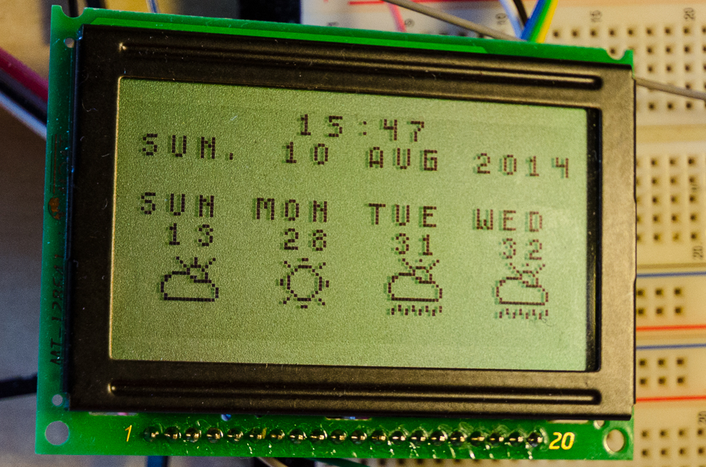
- Displaying current time, date and several days forecast.
1. OpenWeatherMap:
OpenWeatherMap was launched in 2012 by a team of enthusiasts eager to provide free and accessible weather information for any point of the globe. This website has been constantly developing ever since, and you can judge about its possibilities by API supplied: forecasts for five days with calculation of meteorological conditions for every three hours, forecasts for the timeframe up to 16 days, availability of historical data, maps of e.g. nebulosity.
We will use seven days forecast with refresh rate once in 24 hours. In case of large amount of inquiries API OpenWeatherMap may request a key, which may be obtained after registration. But we have no fear. I doubt we will have more than a hundred requests during 24 hours.
To receive a forecast, a GET request is sent to a dedicated address, which for Moscow looks like:
1 2 | http://api.openweathermap.org/data/2.5/forecast/daily?q=Moscow,ru&units=metric&cnt=7 |
Thus, we need to receive forecast for Moscow q=Moscow,ru from API OpenWeatherMap in the metric system units=metric for seven days cnt=7. If we need an answer in JSON, one more parameter should be added: mode=json. But XML is more convenient for us.
1 2 3 4 5 6 7 8 9 | {“cod”:“200”,“message”:0.2284,“city”:{“id”:524901,“name”:“Moscow”,“coord”:{“lon”: 37.615555,“lat”:55.75222},“country”:“RU”,“population”:0,“sys”:{“population”:0}},“cnt”:7, “list”:[{“dt”:1407142800, “temp”:{“day”:28.06,“min”:23.9,“max”:28.06,“night”:23.9,“eve”:28.06,“morn”:28.06}, “pressure”:1011.4, “humidity”:38, “weather”:[{“id”:803,“main”:“Clouds”,“description”:“broken clouds”,“icon”:“04d”}], “speed”:4.61,“deg”:38,“clouds”:64},...]} |
In return, OpenWeatherMap will send us for each day the following:
- day, night, evening and morning temperatures including minimum and maximum;
- pressure in gigapascals;
- air humidity;
- text description of weather and even display icon name
"icon":"04d"; - wind velocity and direction;
- nebulosity per cent.
We only need do parse properly the server’s reply.
2. WizFi220:
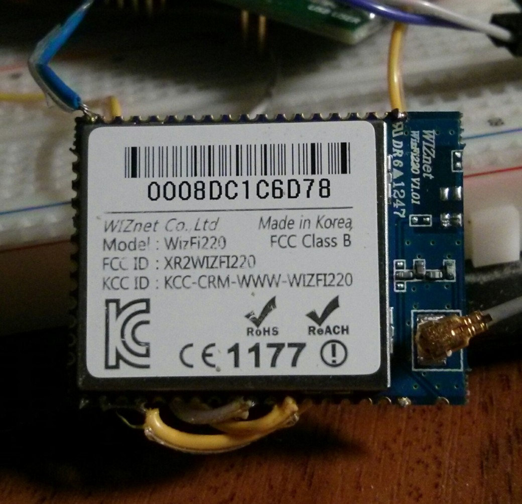
There are two versions of such modules: WizFi220 and WizFi210. They are totally similar except for one item: the first module features higher power of the transmitter resulting in higher consumption.
Their properties are as follows:
- Dimensions 32 x 23.5 x 3 mm.
- Supports 802.11b only.
- Encryption: WEP, WPA/WPA2-PSK, Enterprise (EAP-FAST, EAP-TLS, EAP-TTLS, PEAP).
- Protocols: UDP, TCP/IP (IPv4), DHCP, ARP, DNS, HTTP/HTTPS Client and Server.
- Supply voltage: 3.3 V.
- Consumption:
standby: 34 μA (WizFi210), 35 μA (WizFi220);
reception: 125 mA (WizFi210), 125 mA (WizFi220);
transmission: 135 mA (WizFi210), 250 mA (WizFi220). - Control occurs totally through UART.
If we refer to pinout we can see there ALARM, ADC, and GPIO pins. To make them work, WIZnet, the module manufacturer, recommends you to reflash them by yourself.
The module can be easily switched on: connect pins 1, 18, 31 and 48 (all GND) to earth, 32, 33 and 34 (VIN_3V3, EN_1V8, VDIO) — to +3.3 V, and 40 and 42 (UART0_RX and UART0_TX) — to controller or PC via converter UART <-> USB.
To initialize this module properly, it is necessary to send the sequence of instructions (each instruction should end with carriage return char CR, 0x0D) thereto:
2 3 4 5 6 7 8 9 | AT ATE0 AT+WD AT+NDHCP=1 AT+WPAPSK=SSID,passphrase AT+WA=SSID AT+NCLOSEALL AT+NCTCP=144.76.102.166,80 |
AT— this instruction is needed for check of the module correct operation. After first turning on, the module shall returnAT\r\r\n[OK]\r\n.ATE0disables instruction echo. The module does not return a newly received instruction any more, and only sends in the answer.AT+WDmakes module disconnect from all Wi-Fi networks. Needed in case if WizFi220 should be reinitialized due to whatever reason without reset.AT+NDHCP=1turning on DHCP client. I think there is no need to explain what is that.AT+WPAPSK=SSID,passphraserequests WizFi220 to calculate PSK (Pre-Shared Key) for network and key.AT+WA=SSIDstarts the process of association with network.AT+NCLOSEALLcloses all connections.AT+NCTCP=144.76.102.166,80connects the TCP client to IP address and TCP server port. In this case, it is the address of openweathermap.org.
Thus, we have connected to the server and are ready to download weather by terabytes. But how? And here you need to remember that our WizFi220 only serves as a bridge between our controller and server. We should then realize temporality of the situation and go to Wikipedia to read about GET requests. That’s right. We will get weather data via requests sent to the server.
1 2 3 4 5 | GET /data/2.5/forecast/daily?q=Moscow&units=metric&cnt=7 HTTP/1.1\n“ “Host: openweathermap.org\n“ “Connection: keep–alive\n“ “\n“ |
Blank line in the end is mandatory!
There is not much left — to realize how to make WizFi220 handle this request correctly. For this purpose, escape sequences exist. There are only three of them, but we are going to use the simplest of them:
1 2 | <ESC>S<CID>data<ESC>E |
Here, <ESC> — 0x1B, S and E — abbreviations from Start and End, CID — Connection ID, and data — data to be transferred.
If we insert the above GET request as data, 0 as CID, since we have a single connection with OpenWeatherMap, and send the sequence to module, the request will be sent to the server and the requested forecast will return along with HTTP header.
3. Screen:

The screen is an LCD panel with resolution 128 х 64 pixels and two master controllers K145VG10, produced by OJSC Angstrem similar to KS0108 by Samsung. Why two of them? Because this controller is only capable of controlling 64 х 64 pixel panel. Control RAM of the controller is divisible into pages, columns and lines. Page is a 128 х 8 bit memory space. Screens may require both +5 V and +3 V, which is obvious from label. In my case, supply voltage is +5 V.
Screen connector contains 20 pins with description provided in the list as per following mask: — — — .
- 1 — Ucc — supply — to 5V at Discovery.
- 2 — GND — earth — to GND at Discovery.
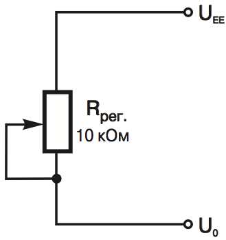
- 3 — Uo — supply input of the LCD panel for sharpness control — to trimming resistor.
- 4–11 — DB0–DB7 — data bus — to PD0–PD7 at Discovery.
- 12, 13 — E1, E2 — choice of controller — to PD8, PD9 at Discovery.
- 14 — RES — reset — to PD10 at Discovery.
- 15 — R/W — choice: read/write — to PD11 at Discovery.
- 16 — A0 — choice: instruction/data — to PD12 at Discovery.
- 17 — E — data strobing — to PD13 at Discovery.
- 18 — Uee — output DC – of DC transducer — to trimming resistor.
By the way, be very attentive when searching documentation for similar screens: e.g. pinouts of MT-12864J and MT-12864A were changed: the former has 1 — Ucc and 2 — GND, while it is vice versa for the latter!
There is nothing complicated in programming this controller: MELT provides examples for its screens. Here is e.g. the screen availability waiting procedure suggested by the manufacturer.
1 2 3 4 5 6 7 8 9 10 11 | void WaitReady(bit l, bit r) { LCD.RW=1; LCD.A0=0; // Reading busy flag LCD.E1=l; LCD.E2=r; // Choosing needed crystals in the indicator Delay(>140ns); LCD.E=1; Delay(>450ns); while(LCD.D.7==1);// Waiting to clear busy flag LCD.E=0;// Clearing signal E Delay(>(1000ns–140ns–450ns));// Minimum allowable interval between signals E=1 } |
Here is the same procedure written by me.
1 2 3 4 5 6 7 8 9 10 11 12 13 14 15 16 17 18 19 20 21 22 23 24 25 26 27 28 29 30 31 32 33 34 35 36 37 38 39 40 41 42 43 44 45 46 47 | #define LCD_SET_RESET_LINE() GPIO_WriteBit(GPIOD, GPIO_Pin_10, Bit_RESET) #define LCD_RESET_RESET_LINE() GPIO_WriteBit(GPIOD, GPIO_Pin_10, Bit_SET) #define LCD_READ_DATA() GPIO_WriteBit(GPIOD, GPIO_Pin_11, Bit_SET) #define LCD_WRITE_DATA() GPIO_WriteBit(GPIOD, GPIO_Pin_11, Bit_RESET) #define LCD_SEND_DATA() GPIO_WriteBit(GPIOD, GPIO_Pin_12, Bit_SET) #define LCD_SEND_COMMAND() GPIO_WriteBit(GPIOD, GPIO_Pin_12, Bit_RESET) #define LCD_SET_STROBE_LINE() GPIO_WriteBit(GPIOD, GPIO_Pin_13, Bit_SET) #define LCD_RESET_STROBE_LINE() GPIO_WriteBit(GPIOD, GPIO_Pin_13, Bit_RESET) #define LCD_CHOOSE_CRYSTAL_0() GPIO_WriteBit(GPIOD, GPIO_Pin_8, Bit_SET); GPIO_WriteBit(GPIOD, GPIO_Pin_9, Bit_RESET) #define LCD_CHOOSE_CRYSTAL_1() GPIO_WriteBit(GPIOD, GPIO_Pin_8, Bit_RESET); GPIO_WriteBit(GPIOD, GPIO_Pin_9, Bit_SET) void waitForLCDReady(uint8_t crystalId) { // Pin PD7 — to inlet for reading crystal status GPIO_InitStructure.GPIO_Pin = GPIO_Pin_7 | GPIO_Pin_5 | GPIO_Pin_4; GPIO_InitStructure.GPIO_Mode = GPIO_Mode_IN; GPIO_Init(GPIOD, &GPIO_InitStructure); LCD_READ_DATA(); LCD_SEND_COMMAND(); if (crystalId == 0) { LCD_CHOOSE_CRYSTAL_0(); } else { LCD_CHOOSE_CRYSTAL_1(); } Delay(1); LCD_SET_STROBE_LINE(); Delay(1); // Waiting for availability while (GPIO_ReadInputDataBit(GPIOD, GPIO_Pin_7) == Bit_SET) { ; } // Changing direction of pin operation again GPIO_InitStructure.GPIO_Pin = GPIO_Pin_7 | GPIO_Pin_5 | GPIO_Pin_4; GPIO_InitStructure.GPIO_Mode = GPIO_Mode_OUT; GPIO_Init(GPIOD, &GPIO_InitStructure); LCD_RESET_STROBE_LINE(); } |
Another important moment: we should draw all symbols output to the screen ourselves. For this purpose, I used a wonderful program from Pyotr Vysochanskyi KS0108_4_0_1 (the last version of January 2010). You may download it here.
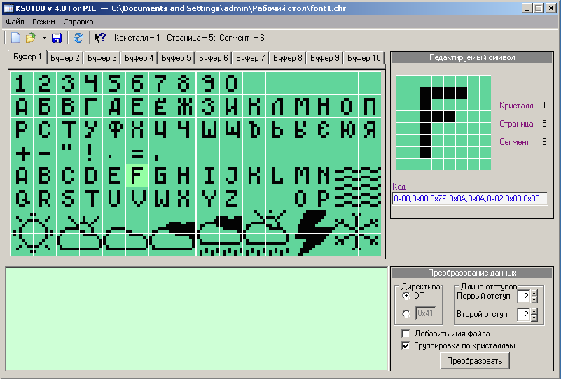
In the right part of the screen below the edited symbol, you can easily see its hexadecimal code, which can be copied and inserted into the code.
Codes of nearly all symbols and all pictograms are in the file symbols.h.
1 2 3 4 5 6 7 8 9 | const uint8_t asciiTable[128][8] = { ... {0x00,0x00,0x7E,0x4A,0x4A,0x34,0x00,0x00}, //66, B {0x00,0x00,0x3C,0x42,0x42,0x24,0x00,0x00}, //67, C {0x00,0x00,0x7E,0x42,0x42,0x3C,0x00,0x00}, //68, D {0x00,0x00,0x7E,0x4A,0x4A,0x42,0x00,0x00}, //69, E {0x00,0x00,0x7E,0x0A,0x0A,0x02,0x00,0x00}, //70, F ... |
In my program, I declared the array uint8_t displayArray[8][128] = {0x00};. Everything to be output on screen is first written to this array, and only then the image is updated.
4. Operation algorithm:
Now, the operation algorithm itself:
- Setting up clocking of I/O ports, USARTs and RTC —
enableClocks();. - Setting up I/O ports mode of operation —
setUpGPIO();. - Setting up USARTs —
setUpUsart();. - Setting up real time clock —
setUpRTC();. - Setting up screen —
initLCD();. - Initializing WizFi220 —
initWizFi220(...);. - Requesting weather data for the first time —
callWeather(...);. - Parsing it and outputting to screen —
parseAndSetDateTime(...);andparseAndSetWeather(...);. - Updating clock time at screen every minute.
- Requesting new weather data every 30 minutes.
Conclusion
Possible variants of project extension:
- Using color screen and outputting e.g. weather diagrams. As you remember, we did not use three-hour forecasts.
- Creating fully-featured weather station and sending own changes to OpenWeatherMap.
- Elaborating printed circuit board and housing (without it, the device looks horrible).
COMMENTS