introduction
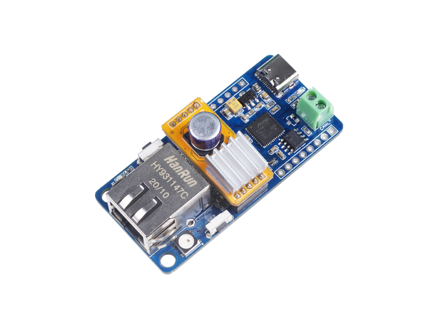
Squama is a series of products. This series of products have a standard appearance, with a general size of 62x30mm. The series integrates an MCU and peripherals with a communication function, which is suitable for IoT-related applications.Squama Ethernet with CAN FD is the second product in the Squama series. The board integrates a high-performance microcontroller based on Cortex M4 and an Ethernet control chip W5500, which can be used by users to develop Ethernet as well as CAN FD applications.WS2812 LED and user buttons are also integrated on the board, which can facilitate some interaction. More importantly, Squama Ethernet with CAN FD supports PoE (Power Over Ethernet), which makes the wiring more concise. Only one network cable is needed to complete signal transmission and power supply.You can use Arduino IDE to develop your application easily.
features
- Powerful CPU: ATSAME51G19A 32bit Cortex M4 core
- Various Hardwired TCP/IP Protocols support: TCP, UDP, ICMP, IPv4, ARP, IGMP, PPPoE
- Flexible compatibility: Compatible with Arduino IDE
- High-Speed Serial Peripheral Interface:SPI MODE 0, 3
technical details
Specifications
- MCU: ATSAME51 32bit Cortex M4 core
- Clock speed: 120MHz
- Flash memory: 512KB
- RAM: 192KB
- EEPROM: No EEPROM
- Input voltage: 5V via USB and 48~57V via PoE
- Output Current @ 5V: 2A
- Size: 62x30 mm
- Weight: 15g (without PoE), 20g (with PoE)
- both CAN-FD and CAN2.0
- Supports 8 independent sockets simultaneously
- Supports Power-down mode
- Supports Wake on LAN over UDP
- Internal 32Kbytes Memory for TX/RX Buffers
- 10BaseT/100BaseTX Ethernet PHY embedded
- Supports Auto Negotiation (Full and half duplex, 10 and 100* based )
- Not supports IP Fragmentation
- WS2812B Led
- Reset Button and User Button
- Grove connector for I2C and UART
Hardware Overview
1. LED indicators:- R: Reset (red)
- P: Power (green)
- L: D13 (blue)
how to use
COMMENTS