Partly due to my interest in doing something like this, and partly because of my interest in Codesys I’ve had it on my mind for a while now to try and connect a second Network Interface port to a Raspberry Pi. So while doing other projects I’ve been thinking , reading, comparing, planning and shopping so that I could finally go ahead and build something up.
Yeah – I know.. there are a few “turn-key” ready to go systems available out there what would do something similar, but really none of them were enticing enough to separate me from my money.
In reality, I have a low level of knowledge and experience on the Raspberry Pi and Linux / Raspberry Pi IOS (Raspian) (I do better in the Windows and Android worlds), no in-depth knowledge of Networking ( I can make things work and build networks, but beyond that I’m a bit over my head), and I’ve only just started making Circuit Boards. For sure, I am not a programmer.
Once I finally decided to move forward with this idea of building something up, and opted to use the WIZ820io / USR-ES1 module, which is based on the Wiznet – W5500 integrated Circuit. This module can communicate with the Raspberry Pi (and other MCUs) using the standard SPI bus. Additionally, it runs off of 3.3 VDC, so it poses ZERO damage risks to my Raspberry Pi.
On designing the circuit board, I opted to build it in a proper “HAT” configuration (shape and capability), and in addition to adding the circuitry for the “WIZ820io module I also added a number of other items which are NOT used in this networking project, but which I can and will be used for other projects in the future.
Supplies:
Raspberry Pi – I used an older Raspberry Pi 3B. Nothing wrong with that.. Mine does have a dead HDMI port, so I run it “headless” using TeamViewer to access it. It works. I strongly suspect that most versions of Raspberry Pi’s will work with this Instructable PROVIDING that they can run more recent versions of Raspberry Pi IOS (Raspian).
Before starting all this, I of course updated the operating system:
sudo apt-get update
sudo apt-get upgrade
WIZ820io / USR-ES1 – The documentation for this is available online from the OEM
PC Board – I used Autodesk Eagle to design the PCB with, and generate the Gerber files necessary for JLCPCB to build the circuit board with. As previously noted, I also added “CAT24C32” Memory Chip to maintain HAT compatibility requirement.
Step 1: Raspberry Pi 3b

As for the Raspberry Pi, I made this project using a standard Raspberry Pi 3b , along with the latest version of Raspberry Pi IOS (Raspian) that I could download and install.
Nothing special there. I’ve owned that unit for a few years, and it’s worked mostly well for me (well – the HDMI video output is dead so I’m forced to run headless using TeamViewer). You should not need to do this.
I suspect that any RPi should be able to connect to a WIZ820io / USR-ES1 – Wiznet W5500 and make this work, as well as many other brands compete in the same market (Beagle Bone, Orange, Tinker, etc) and use a similar model Linux based OS.
I have ZERO experience with any of those. I have little experience with the Raspberry – look where that got me 🙂
Step 2: Interfacing the Wiznet WIZ820io Module to the Raspberry Pi GPIO Bus.

Review the attached images.
The Wiznet WIZ820io module provides two rows of 6 pins each to interface to.
The rows are labeled “J1 and “J2” respectively.
The Data Sheet they provide has a very nice color coded diagram of each pin. This diagram is meant to assist you in connecting those pins to your Raspberry PI GPIO pins. They are pretty well a NAME for NAME match.
The Raspberry Pi pinout can he found here: pinout.xyz
I connected those pins as follows (see attached image):
Of course, since I made an actual circuit board, all Grounds (GND) were connected together. The same goes with the to 3.3V pins – my circuit board connected those together.
A few things of note..
1st – J2 Pin #5 – RSTn – I connected that to RPi GPIO #17(Pin #11) – That was cautionary. I do not believe that it is used .
2nd – J1 Pin #6 – INTn – That is connected to GPIO25 (Pin # 22). This is required, since in the Raspberry Pi IOS configuration step, we’ll refer to this.
3rd – J1- Pin #5 – SCNn – That is connected to the Raspberry Pi “CS0” (Pin # 24). Effectively that gives this module the address of “Module 0” on the RPi SPI Bus. Again, in the Raspberry Pi IOS configuration step, we’ll refer to this.
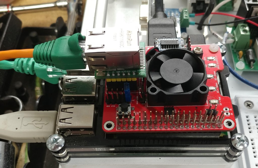
Step 3: My Circuit Board


Attached is the Eagle “Point to Point” schematic I made-up and with which I generated the Gerber Files.
Also attached are images are of the “Circuit Board” I had made-up for this project.
This board will accept a number of different Wiznet products of the WIZ820io style.
Step 4: Raspberry Pi IOS (formerly Raspian) Configuration – Entries in the “boot” Folder
For the Raspberry Pi to “see” the newly installed WIZ820io module on it’s SPI bus, the IOS needs to be made aware, so it can deal with it during “BOOT Up”.
To do this, we’ll simply add two lines to: ../../boot/config.txt
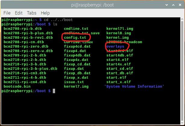
First.. Using a Terminal pane / window ==> ls
cd ../boot, navigate your way to ../boot and list ( ls ) the directory
Reference the attached image.. There you need to look for and confirm the presence of two entries – I’ve circled them in red.
One is a file named: “config.txt”
The second is a folder named: “overlays”
== == == ==
Once you have confirmed the presence of both of these entries, you can continue to the next step
Step 5: Raspberry Pi IOS (formerly Raspian) Configuration – Entries in the “overlays” Directory

Change Directory to the “overlays” directory”
Type: cd overlays
After striking the “enter” key, that will take you to the “overlays” folder (see attached image).
List the contents of the directory.
Type: ls
After striking the “enter” key, you should see a long listing of the contents of that directory. The listing maybe alphabetical.
(see attached images (2 of)). Notice that nearly ALL the files are named with an extension of : *.dtbo you may also notice a few named with an extension of: *.dtb
These are ALL “Device Tree” overlay files
You need to confirm the presence of two “overlay” files (see attached image files).
1st – a file named: anyspi.dtbo (for this one, you may need to use the scroll bar in the right margin of the window to scroll back to the top and find the alphabetically ordered anyspi.dtbo).
2nd – a file named w5500.dtbo
== == ==
If you can confirm that both of these files are present, then you are in good shape and can return to the ../boot directory.
Type: cd ../ after striking the ENTER key, you should be taken back to the /boot directory.
List the directory to confirm: type: ls and strike the ENTER key
Step 6: Raspberry Pi IOS (formerly Raspian) Configuration – Edit File Named: Config.txt

In the ../boot directory, we can now work to make a couple of small edits to the file named: config.txt
We’ll first call on the “nano” editor as a “super user” (sudo)
sudo = ‘superuser”
nano is the text editor that we’ll be using
and as noted, config.txt is the file we want to edit.
Type: sudo nano config.txt and strike ENTER.
This will bring up the editor, and display the content of the config.txt file. If the editor does not open, or opens empty, then exit (if in nano) and double check your spelling.
If all went well, you should see something like in the second attached image. “nano” will be displaying the very “top” of the file. you’ll need to scroll down to the very bottom.
At the very bottom of the file, add the two “dtoverlay statements” below:
dtoverlay=anyspi,spi0-0,dev=”w5500″,speed=30000000
dtoverlay=w5500
Double check all spelling, and if it matches, press the two keys “Ctrl-x” to exit.. and answer appropriately to save and exit.
At the next boot-up (and for all boot-ups afterwards if those two statements remain there) the operating system will now also call on the overlay named “anyspi” and the the overlay named “w5500“.
The overlay “anyspy” prepares the operating system to use the SPI0-0 bus (that is where we previously physically connected the WIZ820io to. The “-0” specifies it to use address “0” – recall that we previously connected the WIZ820io pin #J1-6 to the RPi GIPO “CEO” (Pin #24).
The overlay “w5500” tells the operating system how to deal with the W5500 integrated circuit located in the WIZ820io module. It also defines to use RPi GPIO25 (Pin #22) as the INTn signal. Recall once again that we previously made this connection.
This kind of information can be found in various files, like this one example found on GITHub.
== == ==
Time to reboot the RPI, and make all of this take effect.
Step 7: We’ve Re-booted. I Hope You Are Smiling.

If all went well, your RPi should have re-booted normally. Smile.
Time to check if the IOS loaded the two new overlay files, and if it recognizes the attached WIZ820io module.
Once again open a “Command” window.
This time at the prompt , type ifconfig (or use the newer “ip” command), and the strike the Enter key.
You’ll probably get a long response, so you’ll need to scroll back up to the top.
Back at the top, look for the two sections:
One named eth0, and a second named: eth1 – see attached image.
In my system, eth0 is the Ethernet port on the RPI. eth1 is the new WIZ820io Ethernet Port.
== == ==
If you are seeing the two ports, then so is the RPI. Notice in the attached image, eth1 has sent packets, and without errors.
I’ve tested this by disconnecting the original port cable, and using the browser to go to YouTube and other websites.. It works. I’ve also “ping’d” it from a few different devices and it works.
== == ==
If you are not seeing eth1 (or something similar) – other than eth0 on an RPI3 or RPi4, then try going back and double checking that the config.txt was properly edited and saved. Make certain that the two overlays are in place, and spelling is correct (no capital letters where I don’t have them – capitals matter in this system).
== == ==
If the two ports are present, then there may be a bit more configuration work to do… on to the next step….
Step 8: Raspberry Pi IOS (formerly Raspian) Configuration – Setting IP Address
This is a bit out of my wheel house, so at this time I’m not able to provide guidance.
Just know that there are countless websites, YouTube videos, and message boards that provide this kind of information.
but.. you may want to check on and do a few things here.
1 – Double check the IP address that your new port currently has. was it assigned by your DHP server, or is it the default IP – something in the range of: 169.254.xxx.yyy ? Is it something else??
2- Do you want a Static (fixed) IP address or a Dynamic IP address (assigned by your DHCP server).
Check the switch / router that your RPI is connected to.. does it see your new port? can it “Ping” it? (be sure to disconnect the original port cable if you do this – otherwise the RPi may fool you).
Use ifconfig (or the newer “ip” command) to see that the data coming and going is looking “normal” (so to speak) and without an undue number of errors.
== == ==
Lastly.. I believe that it is the w5500.dtbo assigns a MAC address to the WIZ820io / W5500 module.. but I cannot say for certain if that is where it happens. I could not immediately find details on that.
For me it appears that a different MAC address is assigned each time it boots up. I personally do not like that, and consequently there are things that can be done to set the Mac Address (the program “macchanger” for example or setting it through the ip / ifconfig commands). If any of you find a “boot-up” / “crontab” solution to this, I would be happy to hear about how you do it if you are open to sharing.
You can see mine in the image.. When I look-up the Mac Address vendor for eth0 ==> b827eb, it comes up as the Raspberry Pi Foundation. The vendor for eth1 ==> fa9770 comes up as unknown, so obviously, it was generated on my Pi at some point..
Step 9: Conclusion
Thanks for checking out this Instructable.
I learned quite a bit working through this little project.
Should you have any questions, or may be interested in buying one of the boards I made-up (populated or not), I have some extras that are for sale and which we can discuss.
In any case, I urge you to leave comments, suggest corrections (typos or methods or??)
Most-certainly, if you make this for yourself, I would be very pleased to see photos of how you tackled it, and your end results / purpose.
Thanks.
P.S.: Thanks to this fellow for the guidance and ideas.
Step 10: DTBO Files
Two files to add to your “overlays folder – Needed for Steps #4 and #5
COMMENTS