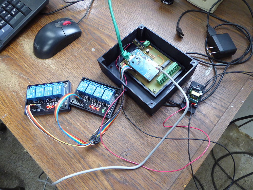
The board uses an Arduino Nano as the controller. A socket is provided to plug in one of the small W5500 modules commonly available on eBay/Aliexpress. The socket just breaks out the SPI bus with additional power and ground.
At the top left is a small power supply section for an optional 7805 linear regulator if the board is to be powered from a non-5V source.

The real utility are the input terminals on the right side. There are 8 active-high opto-isolated inputs which can be connected to any on/off input such as a button, switch, door contact, motion sensor, relay contacts, etc. The firmware loops through all the inputs every 50 mS and then simply reports their state back via MQTT if the state has changed. Additionally it sends a hold time in mS if the state changes again within a pre-determined timeout. In this way it supports button press duration detection for different actions based on long, short, etc. press. Being opto-isolate, then have 1000V isolation in case of surges and are very noise immune. No “ghost switching”.

At the bottom are 8 digital outputs, some of them supporting PWM, to drive relays. If I need to control something else such as a WS2812 LED strip, then that just gets compiled into the firmware and uses one of the output pins.Yeah, the Ethernet card sort of covers them so I just bend them out a few degrees. Also the serial port is broken out (to the left of the output pins) to provide debugging serial output, and serial input from things such as RFID readers.

I use one or more of these per room to provide all the basic I/O needed, the supplement with things such as other sensors RGB bulbs as required. So far, these boards have been incredibly reliable. I’ve never needed to reboot one and telemetry reports uptimes of 280+ days on the boards I haven’t reset for one reason or another (adding lights, etc.)
As I am slowly gutting every room of my house, each room gets a master control box where all conduits lead that contains one or more of these boards.

Seems that 95% of home automation comes down to taking a user input from a button or switch, then controlling one or more relays.  So most of my control runs through these boards.
But, I’m bumping into limits in memory using the Arduino Nano. Start hanging sensors off of them like BMP280 (or…ugh…DHT22) and an RFID reader and the poor Nano is out of RAM and almost out of program space. So I’ve designed a new board, which is another topic entirely.
COMMENTS