Hello everyone!
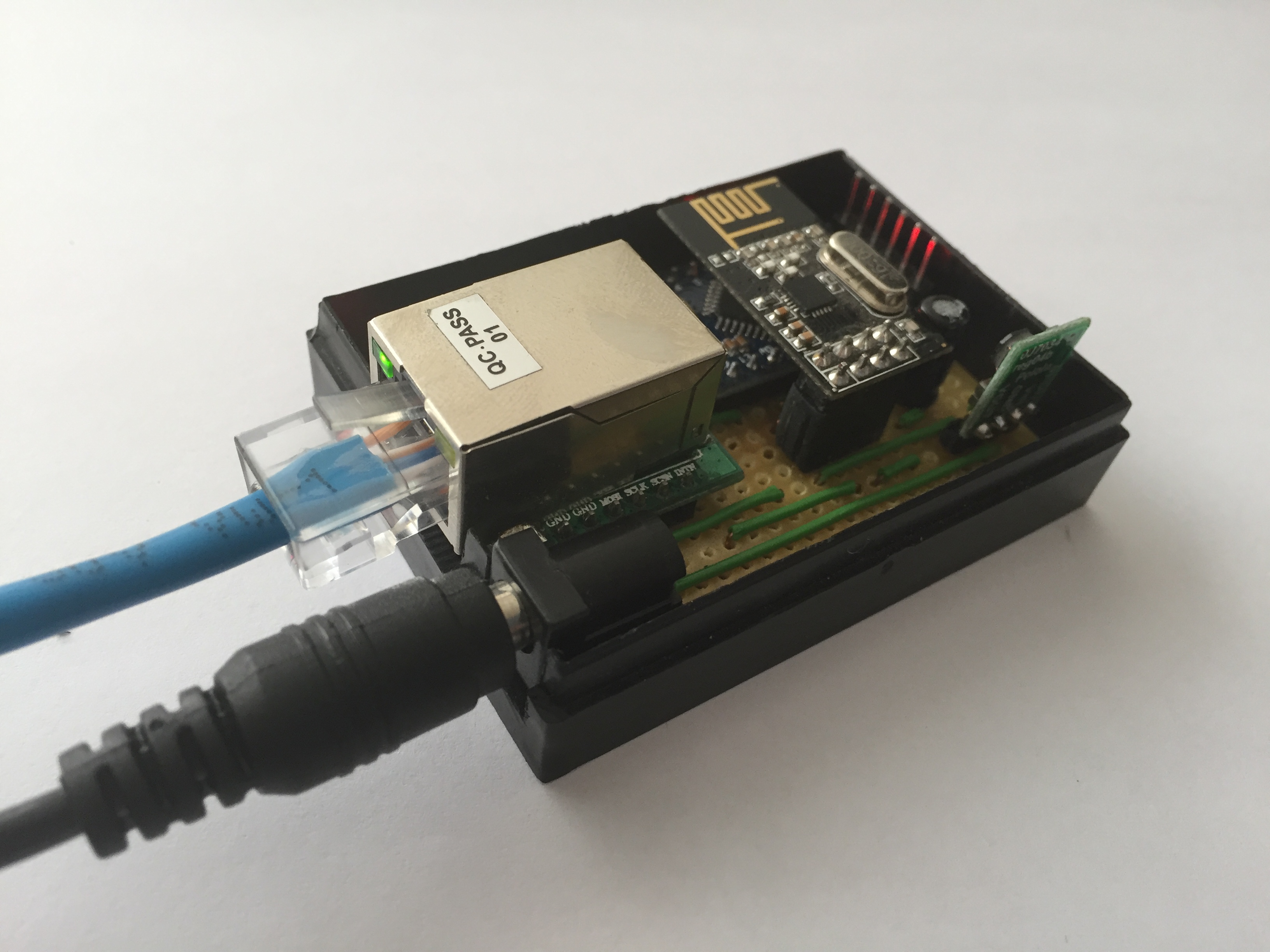
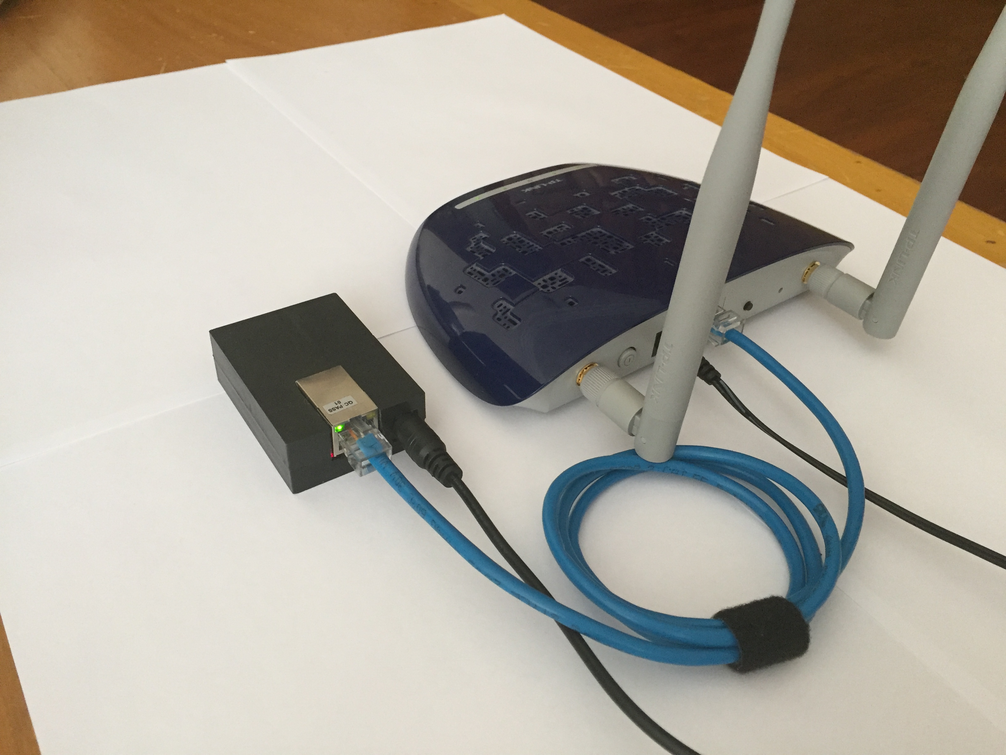
Just wanted to share my Ethernet Gateway build. It became pretty neat, I think.

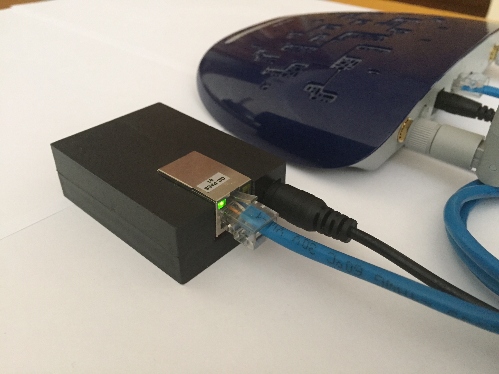
Connected to my WIFI extender.
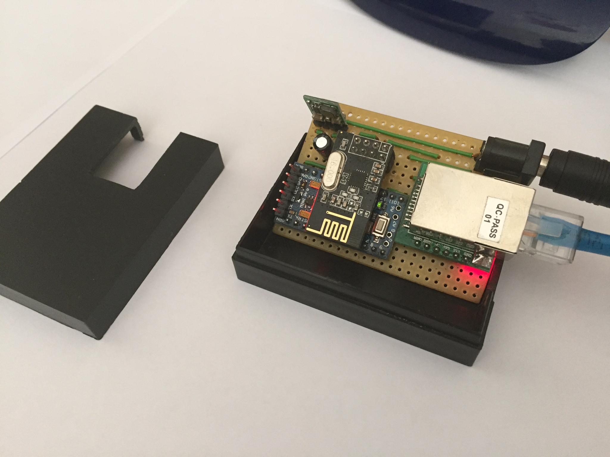
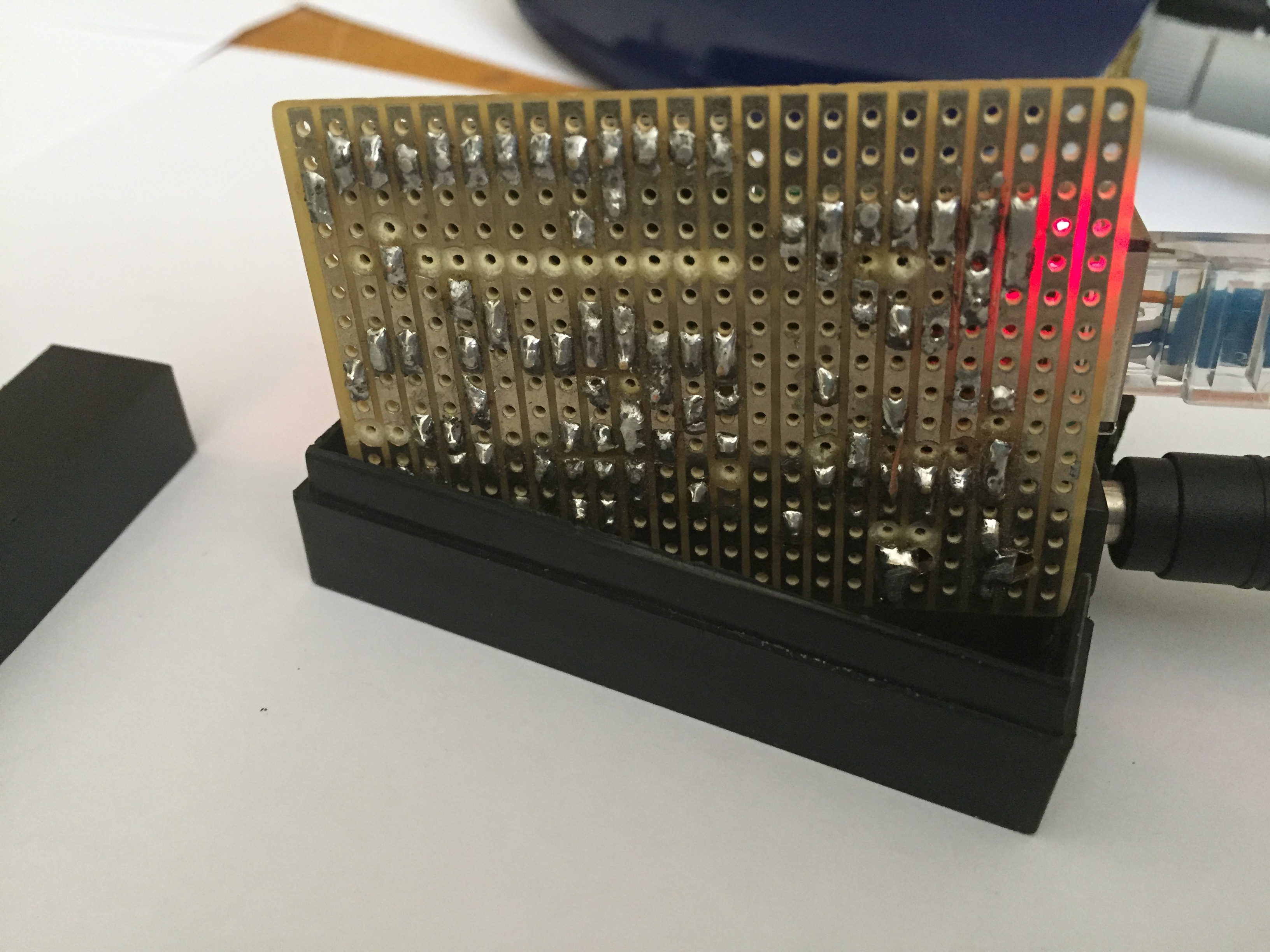
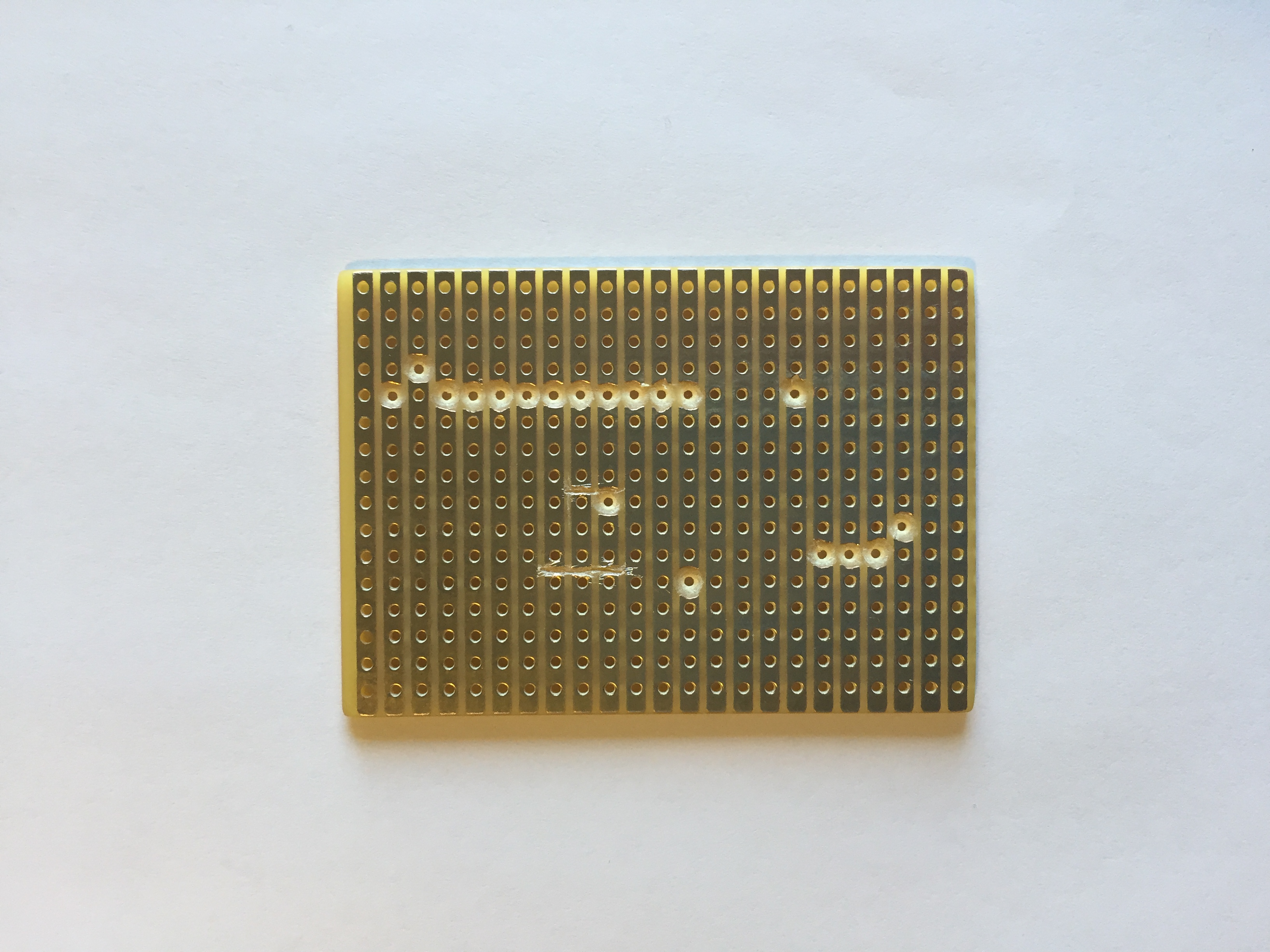
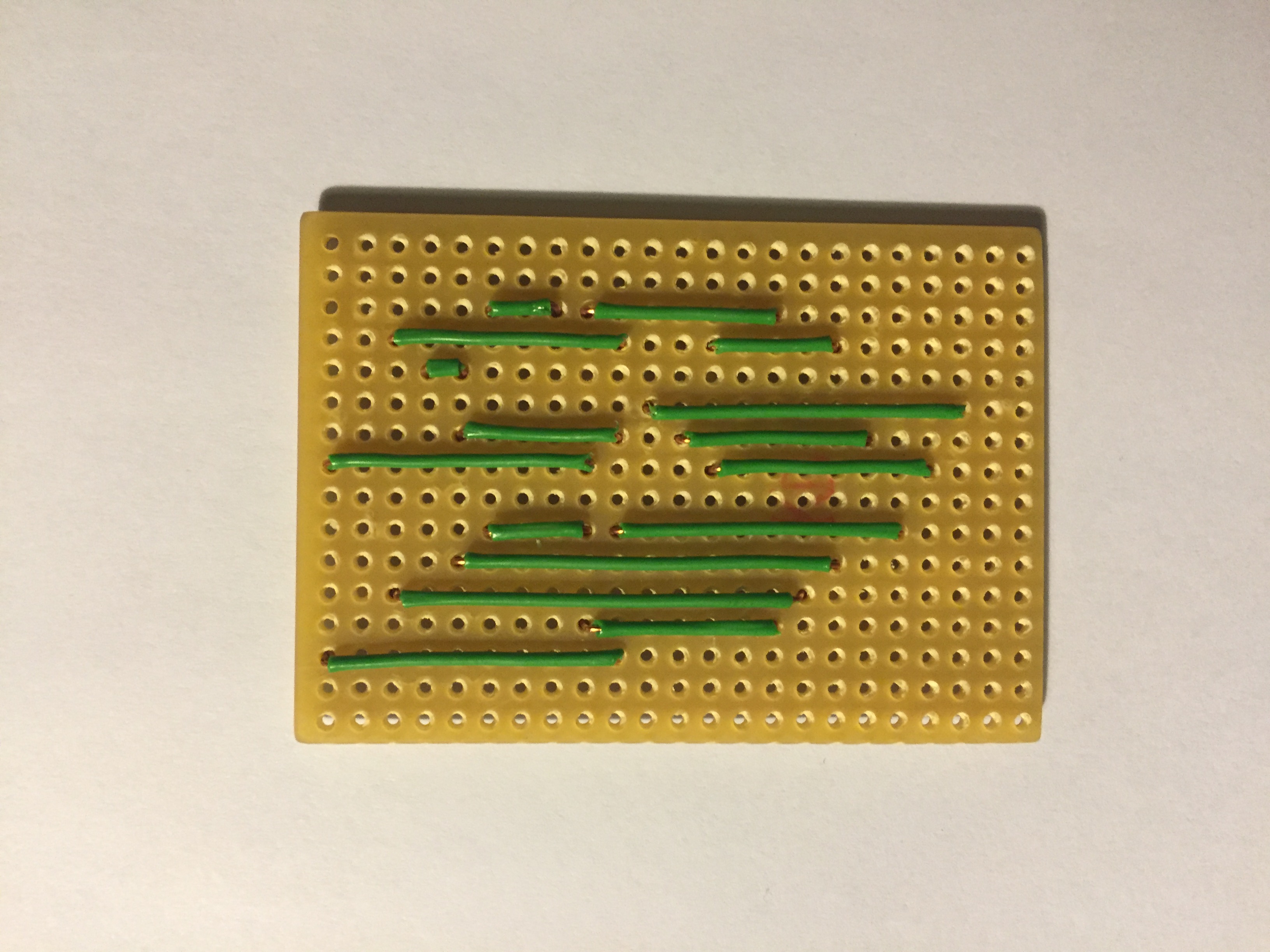
I’m using a Vero PCB Prototyping Board with copper strips. It makes it easier to solder and less cables.
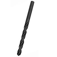
To cut the copper strips on the Vero board I’m using a 5mm drill bit and my finger tips:
Example from a Vero Board Project:
You can buy them for example from here: Ebay
I’m using a W5500 Ethernet Module instead of W5100.
A W5500 Ethernet module is more compact, but a little bit more expensive.
If you’ll use a W5500 Module as I do, you need to replace the Arduino Ethernet library first.
I’m using the following GitHub library from WizNet:
https://github.com/Wiznet/WIZ_Ethernet_Library
Use the Arduino IDE 1.5.X branch.
Replace everything in the original Ethernet Library (Ethernetsrc directory). If you’re using Windows they should be in following directory:
C:Program Files (x86)ArduinolibrariesEthernetsrc
In the file W5100.h located in Ethernetsrcutility it’s preset as a W5500 WizNet chip:
//#define W5100_ETHERNET_SHIELD // Arduino Ethenret Shield and Compatibles ...
//#define W5200_ETHERNET_SHIELD // WIZ820io, W5200 Ethernet Shield
#define W5500_ETHERNET_SHIELD   // WIZ550io, ioShield series of WIZnet
For my Vero board design I made the drawing in Excel. It works pretty well for me. 
Have a look at my Excel file attached here:
0_1453581415262_MySensor Ethernet GW Circuit Board.xlsx
I’m using an Arduino Pro Mini 3.3V 8MHz.
The Voltage Regulator used in this design (D24V3F3 3.3V) is from Pololu.
Please note that the internal Voltage Regulator in the Arduino Pro Mini isn’t powerful enough to run the W5500 Ethernet Module.
COMMENTS