How To Make The Energy Meter
There are essentially three elements to this project which you will need to assemble, the LCD screen, the Ethernet shield and finally the current sensors.
The Ethernet shield simply plugs into the Arduino board and picks up on the pins required through the pin headers.
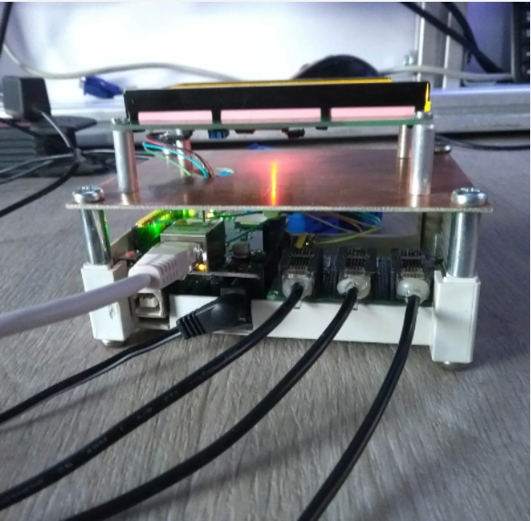
The LCD screen can be mounted onto a board or breadboard. Filip has built a neat box around his Arduino and Ethernet shield with a panel on the front on which the LCD screen is mounted. The LCD screen is driven using the Arduino’s built in library and can be connected by following this guide – connecting and LCD screen to an Arduino. The LCD screen used here is slightly different as it is a larger, serial screen but the principle remains the same. You’ll also have to pick up on the pins which are not being used by the Ethernet shield.
Finally, you’ll need to add your burden resistor and voltage divider circuits to your current sensors.
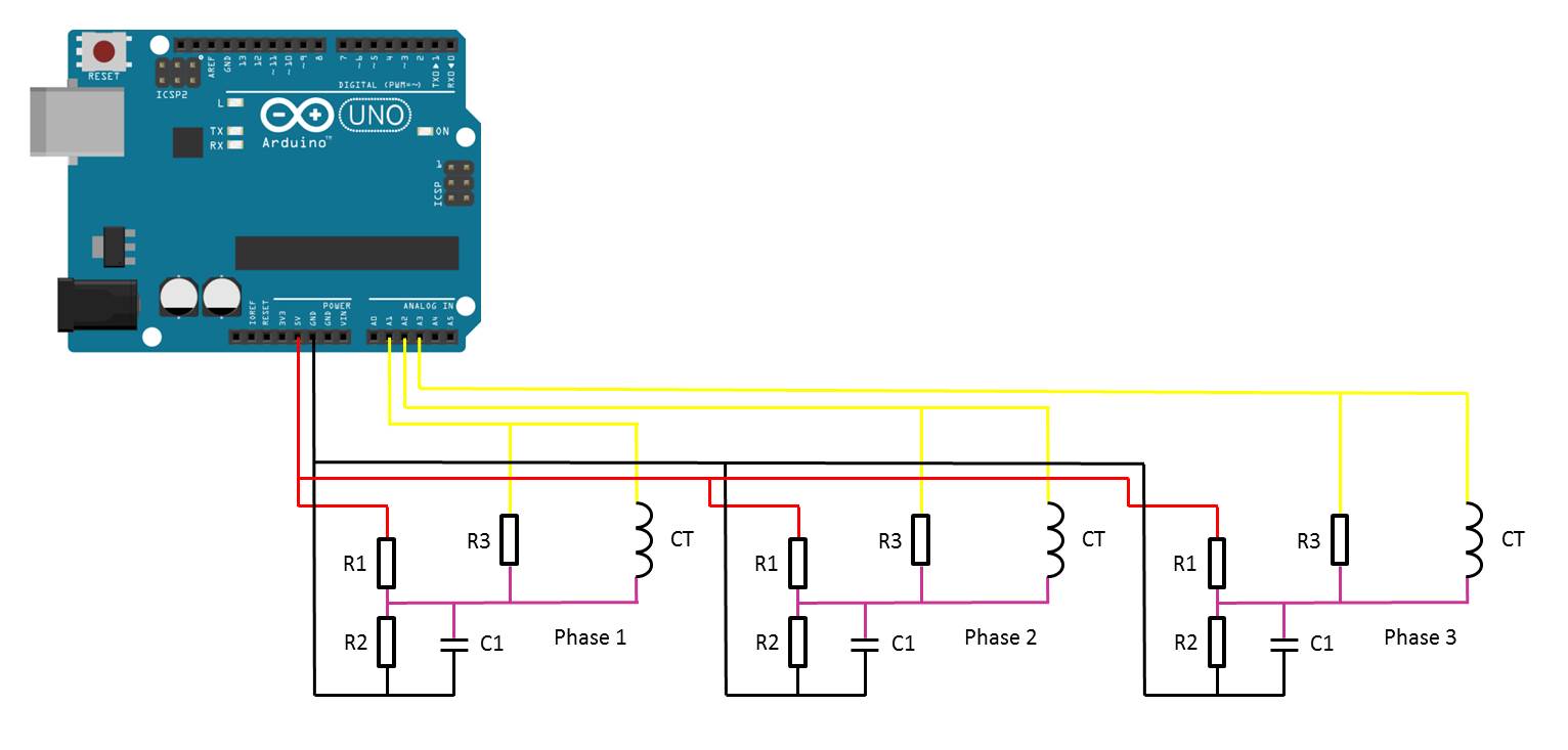
The basic circuit for the connection of the CTs to the Arduino is shown below:
Once you have connected all of your components, you need to connect your sensors onto the supply you want to monitor. For connection to a typical 3 phase mains supply, connect one CT around each of the phases as shown below.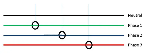
NB – Be careful when connecting the CTs to your mains and make sure that the power to your board is switched off before doing anything in the mains box. Do not remove any wires or remove any screws before checking your local regulations with your local authority, you may require a certified electrician to install the CT for you.
If you’d like to measure a larger or smaller amount of power more accurately, you’ll need to select different CTs. There is a detailed guide to selecting different CTs and their associated burden resistors in the original post.
Upload the Sketch
Now you can upload your sketch onto your Arduino, if you haven’t uploaded a sketch before then follow this guide on getting started. Here is the link to download the code – EnergyMonitorEthernet
Calibrate the Current Reading
As mentioned above, because your setup, CTs , resistors and input voltages may be different, there is a scaling factor in the sketch for each CT which you will need to change before you will get accurate results.
To calibrate your energy meter, you need to be sure that the current that your meter says is being drawn on each phase is what you expect is actually being drawn. In order to do this accurately, you need to find a calibrated load. These are not easy to come by in a normal household so you will need to find something which uses an established and consistent amount of power. I used a couple of incandescent light bulbs and spot lights, these come in a range of sizes and their consumption is fairly close to what is stated on the label, ie a 100W light bulb uses very close to 100W of real power as it is almost entirely a purely resistive load.
Plug in a small light bulb (100W or so) on each phase and see what load is displayed. You will now need to adjust the scaling factors defined in line 20 accordingly:
double calib[3] = {335.0,335.0,335.0}
In this case 335.0 for phase 1, 335.0 for phase 2 and 335.0 for phase 3 have been used as a starting point. They may be higher or lower depending on your application. Either use linear scaling to calculate this figure or, if you’re not good with math, play around with different values until the load you have plugged in is shown on the energy meter’s screen.
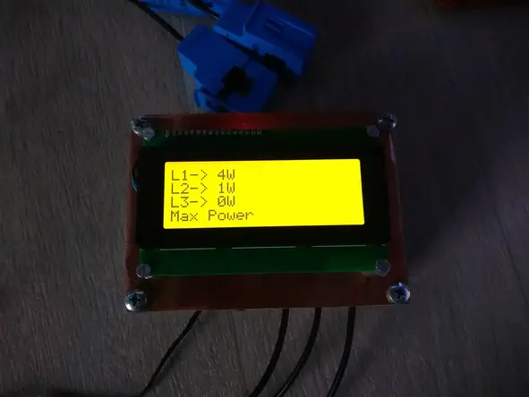
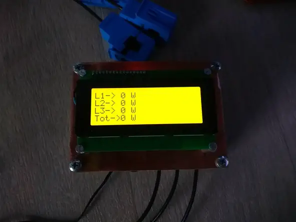
The Energy Meter In Operation
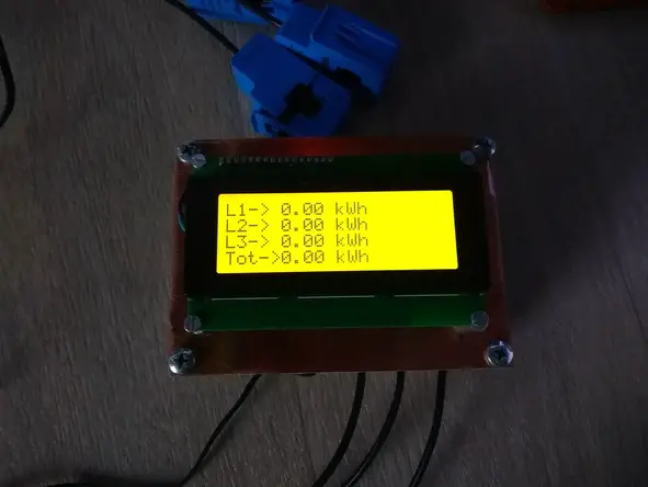
Once you have your energy meter calibrated and the scaling factors have been uploaded onto the Ardunio, your meter should be ready to connect and leave to monitor your energy consumption. Here are some photos of Filips completed energy meter in operation.
COMMENTS