Ethernet and USB board using PIC18F27J53 and W5200
We conducted an experiment to control WIZNET ‘s WIZ820io (W5200) , which is frequently used as a wired LAN module for Arduino, with a PIC microcomputer. Since the W5200 implements TCP / IP protocols internally, it is possible to reduce the program memory load of the MCU (Micro Controller Unit).
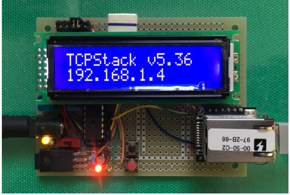
By the way, WIZnet sells an Ethernet PICtail Board using W5200, and the W5200 driver to be added to Microchip TCP / IP Stack is provided by WIZnet’s site. The goal this time is to create a new experimental board consisting of PIC18F27J53 and WIZ820io (W5200), capture the IP address assigned by the DHCP server, and confirm that the NetBIOS Name Service (NBNS) can be used.

PIC18F27J53 <— SPI —> WIZ820io (W5200) <— Ethernet —> Local area network
<< Architecture of the Ethernet board >>
The Ethernet module, WIZ820io, is connected with the microcontroller, PIC18F27J53, using the Serial Peripheral Interface (SPI).
Clock and pin connection of PIC18F27J53 :
The system clock of 48MHz is derived from the external ceramic resonator of 4MHz using the PLL module.
LED : RB1, RB2; Switch (pull down) : MCLR, RB3;
LCD (SC1602BBWB-XA-GB-G) : RS – RC6, R/W – GND, E – RB6, Data bus : DB4 – RB7, DB5 – RC0, DB6 – RC1, DB7 – RC2, VDD – 5 volt
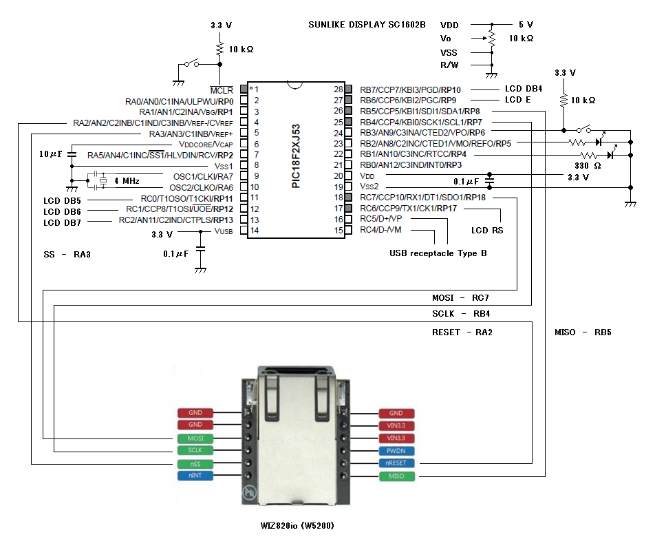
WIZ820io :
RESET – PIC pin 4 (RA2)
SS – PIC pin 5 (RA3)
SCLK – PIC pin 25 (RB4/RP7 assigned to SCK1)
MISO – PIC pin 26 (RB5/RP8 assigned to SDI1)
MOSI – PIC pin 18 (RC7/RP18 assigned to SDO1)
<< Sample code for the Ethernet board with W5200 >>
(Compiled by the C18 under the large code model on the MPLAB X IDE)
In TCPIPConfig.h, STACK_USE_DHCP_CLIENT, STACK_USE_NBNS and STACK_USE_TCP have been defined in this project. Consequently, the test board can practice the communications-protocol of DHCP Client and NBNS.
The default network configuration in TCPIPConfig.h must be adjusted to your local network (MAC address, IP address and so on).
Example above:
NetBIOS Name = PIC18F27J53
Default MAC address = {0x00, 0x04, 0xA3, 0x00, 0x00, 0x00}
Default IP address = 192.168.1.10
Default subnet mast = 255.255.255.0
Default primary DNS = 192.168.1.1
Default secondary DNS = 0.0.0.0
The connection to the Ethernet board can be checked by the ping on the Command Prompt of your Windows PC.
<< Summary in Japanese >>
The WIZnet W5200 hardwired TCP / IP driver used in this experiment required some modifications .
When asked about the cost-effectiveness at the moment, WIZ820io (W5200-equipped module) will be better than ENC28J60 Ethernet LAN Network Module For Arduino SPI AVR PIC LPC STM32. Because programming only uses firmware provided by an amateur, it does not have the qualities to evaluate performance and can only be evaluated in terms of cost in hobby-use.
A strange noise was also recorded together in the video. Please check this.
Thank you for various related technical diagrams & detail explanation.