
The Setup
The Sony Spresense board don’t have an Ethernet peripheral which is something we need for the web camera project. There might be many options out there to provide Ethernet connectivity but not all might serve for our purpose, been the speed and large amount of data transfer our makers that need to be maximized.
Based on previous experience projects, I have found Wiznet modules great for the Job, actually the experience with other technologies shows that the camera acquisition is more of the bottleneck to have a video stream than is the Ethernet connectivity when using Wiznet modules. Another advantage of using Wiznet modules was the easy implementation either from Hardware but more important from Firmware point of view. The last is specially true when using the Arduino IDE.
For the video stream we need the Spresense module with Main board and camera module, for the Wiznet module we have choose Wiz550io.
Hardware Hookup
The hardware is not complicated after sorting out a few issues explained below.
The Spresense SPI port that uses Arduino IDE is accessible using the Main board and has some limitation in speed compared to Wiz550io module which can be clock up to 80MHz. After starting testing the connectivity I noticed that it works intermittent, sometimes the library was not working at all, I play with speed and noticed that at low speed such 2 MHz it was more the times it works than at higher speed. This make me thing it was a hardware problem.
The Spresense documentation (section 4.7) mention that the I/O lines of SPI uses a level converter device, which I have check to be LSF0204x from TI. The device per se don’t seems to be the cause of problem, the problem seems to be an impedance matching between the W5500 device and the pull ups used, perhaps the current driving needs of Input lines of W5500 are not fulfilled. After using a couple of 74AHC1G125 single gate buffer device from TI for the Clock line (SCK) and Data line (MOSI), the issue seems to be solved at least to achieve a reliable operation at 14MHz.
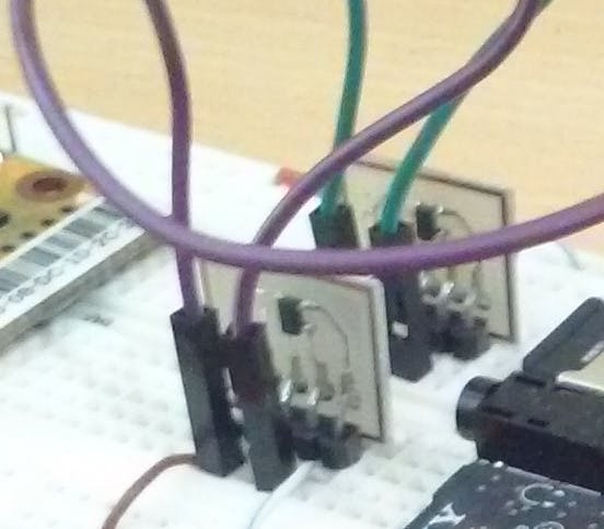
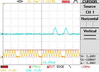
The clock signal with and without the buffer driver can be seen below in a scope trigger capture. There is noticeable difference which might explain the issue. Unfortunately I haven’t a Quad gate buffer such SN74HC125 to test with all high speed lines to check how high the clock can be driven, but also it might not be good to test using a breadboard.

SPI4 is the port used by Arduino IDE and is located in the normal position you would find SPI for Arduino Uno R3. Signal line connections are similar to Arduino. One important difference is that Arduino wiznet library uses an I/O to drive the Chip Select pin. This is the suggested way to drive SPI for W5500 IC since CS signal should be active low during a transfer that might consist of several byte cycles. Because of this reason, we cannot connect the CS pin 10 of Spresense, normally labeled SS for arduino pinouts, as this pin is automatically handle by SPI4 peripheral of CXD5602 MCU, this is explained in section 3.8 of Spresense arduino developer guide.
Here is the wiz550io pinout for reference, but more info here.
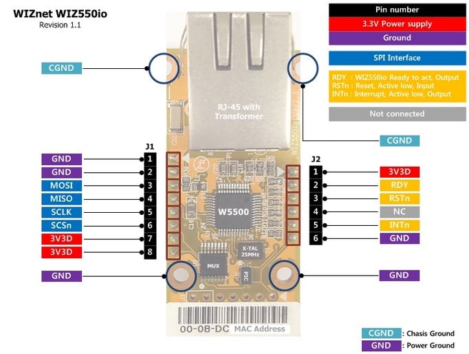
The connections end up been:
Spresense MOSI (D11) -> Wiz550io J1 – pin 3
Spresense MISO (D12) -> Wiz550io J1 – pin 4
Spresense SCK (D13) -> Wiz550io J1 – pin 5
Spresense MOSI (D8) -> Wiz550io J1 – pin 6
Notice that we leave D10 open and use D8 for CS. This will require some change in arduino firmware library or sketch.
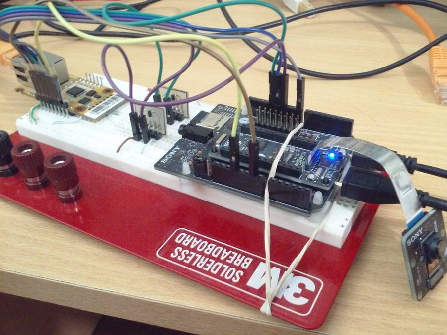
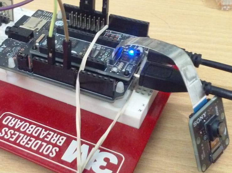
The firmware application needs and SD card as well as camera module connected. In order to have it close to Wiz550io the Main board is placed on top of breadboard as shown below.
COMMENTS