components
details
the operation is the same for the 3 assemblies
Reception of Artnet frames conveyed by an rj45 cable (ethernet)) and a universe in output Dmx protocol on xlr
but I recommend the assembly with screen and interface for the price of an oled in addition, you have a much more versatile assembly.
– 1st version the choice of the universe this fact to the programming
– 2nd version the choice of the universe this fact by dip-switch
– 3rd most recent version the choice of the universe this fact via a web interface (choice of the universe, subnet, net, IP address, dhcp or not …). plus an oled screen indicating the IP address
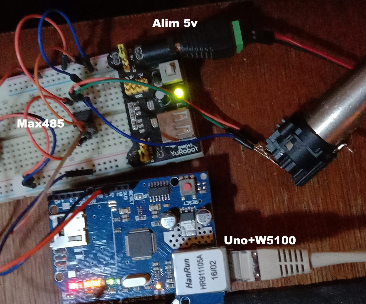
Prototype shield with 5v power supply, isolated dmx output
( optional wifi with esp-01 module )

No difference in operation between the 3 versions, they do their job.
hardware level for the first 2 assemblies:
1 x Arduino Uno ( or clone )
1 x W5100 Ethernet Card
1 x Dmx out Module ( see DmxIn & DmxOut page )
1 x 5v Power Supply
and for the most recent in addition:
1 x Oled Screen 128×32
Mount 3 (with Oled) can be found on github on the ArtGateOne page
Open Arduino, connect the Uno board alone (without the ethernet shield or the DmxOut module).
If your Uno has already been used to erase the EEPROM memory, (open > example > EEPROM > EEPROM_CLEAR) . “
Open the “ArtGateOne_DMX_1.3.ino” file,
you can choose fixed IP address or with DHCP in the setup a la line (a priori the parameters can be changed with the web page)
EEPROM.update(512, 0); DHCP 1=off, 0=on
if you choose fixed address it is the following 4 lines ( ip address 2.0.0.10 )
EEPROM.update(513, 2); IP
EEPROM.update(514, 0);
EEPROM.update(515, 0);
EEPROM.update(516, 10);
Upload the program.
wired your assembly
OLED DISPLAY I2C
Vdc => 3.3v or 5v (depending on your oled)
Gnd => Gnd
SCL => A5 (arduino uno)
SDA => A4 ” ” ” “
Max485 (or sn75716 or a DmxOutmodule)
Ro (pin1) => not connected
Re(pin2) => 5v
From(pin3) => 5v
Di(pin4) => Tx (D1 arduino uno or pin 6 optocoupler)
Gnd (pin5) => Gnd + Pin1 xlr
A(pin6) => Pin3 xlr
B(pin7) => Pin 2 Xlr
Vdc (pin8) => 5v
for the dmx part see DmxOutpage, the rest this summarizes to a 5v alim, an alim3v3 and connectors

with your computer open the page
of the IP address you will have access to the setup (at home with Windows 10 and Firefox the interface opens but it is impossible to save the settings, with Edge it works…??)

Mount 2 can be found on github on the Artnet to Dmx page
You can do like me, in the assembly it is provided 4 leds ws2812b for signaling (they light up at startup …. I deleted them! )
1: in my version arnettodmx.ino (link to the modified file) I disabled all lines for LEDs,
2 : I added the selection of 16 universes with 4 dipswitches (see page Address) connect to pins A0 to A3.
If you keep the original ino file, the choice of the universe does this to the programming, modify the line
byte UniverseID = {0};
In case of special reason you can change the number of Dmx channels as well as the position of the 1st channel
const int number_of_channels = 512; //512 for 512 channels
const int start_address = 0; 0 if you want to read from channel 1

documents
Code
ArtGateOne-DMX 
Artnet_to_DMX
COMMENTS