

While the world’s best minds argue about the development of the Internet of Things and promise fabulous profits to the high-tech companies involved in this process, we also decided not to sit idly by. Under the cut – a story about prototyping a light bulb control device based on the WizFi250 Wi-Fi module .
First, a little about the WizFi250 Wi-Fi module itself. Appearance – in the photo:


The module supports IEEE 802.11b / g / n standards and is controlled by AT commands via UART (or SPI) or via the WEB interface. A full description of the WizFi250 AT commands can be found here .
The module has a PCB antenna, but an external antenna can also be connected. Switching between antennas – automatic or by command AT + WANT. The PCB antenna can be cut off (there is perforation) – then the dimensions of the module will be reduced to 17 x 20 mm.
Wired interfaces: UART, SPI, GPIO.
Manufacturer – WizNet, Korea, here is the datasheet of the WizFi250 module .
For testing, there are boards in the style of Arduino UNO Wi-Fi shield:

But exactly “in style”, since they need to be slightly modified to be used together with the Arduino. This is the board we will use for prototyping in conjunction with the Arduino UNO board.
In general, the plan is as follows: to communicate via Wi-Fi, use the WizFi250 module, to control the module and the light bulb – Arduino UNO, transmit control commands from the phone or tablet via Wi-Fi in the form of UDP or TCP packets. By the
way, the module has 2 useful indicator outputs:
1) WiFi_STATUS: low level – Wi-Fi is running, high level – Wi-Fi is off.
2) MODE_STATUS: high level – command mode (Command Mode), low level – data mode (Data Mode).
On the debug board, these signals are displayed on the “Wi-Fi” and “Mode” LEDs, respectively, which is convenient for debugging.
The supply voltage of the WizFi250 and the inputs-outputs are 3.3 V. The Arduino UNO is five-volt, that is, to control the Wi-Fi module, you need to match the levels. On the WizFi250 debug board, two TXS0104EPWR four-channel level converters are installed, one of which, IC4, is used for the SPI interface, the other, IC5, for the RESET and GPIO14 signals of the Wi-Fi module. But the conversion of the UART interface levels on the WizFi250 debug board for some reason is not provided … This is what I had in mind when I wrote about a small revision.
In theory, to convert the levels of the Rx and Tx UART lines, you can try to use the remaining two channels of the IC5 converter, but I did not want to solder to the thin legs of the level converter microcircuit and modify the debugging, so we used the old old-fashioned way of converting signal levels using a pair of transistors: The

circuits are simple, maybe the only trick is to use a 1kΩ resistor (R3) at the output of the 5V -> 3.3V converter. When using a larger resistor, the circuit does not work correctly, all this is due to the fact that at one point there are two outputs: FTDI FT232 microcircuits and our homemade products. Not good, but quite acceptable for the layout.
As a result, our WizFi250 debug board with a homemade Voltage Level Translator looked like this:

The module can operate in two modes: an access point (AP, Access Point, when other Wi-Fi devices are connected to it) or a client (STA, Station, when it connects to an access point itself).
You can set various security (encryption) settings, enable / disable the internal WEB-server.
The module supports UDP Server / Client, TCP Server / Client, TCP Secured Server / Client modes (SSL is used).
Either the data mode can be set (Data Mode, transparent mode, clean data that comes via TCP or UDP is output to the UART of the module, the module does not accept the control command), or the command mode (Command Mode, data is sent and output to the UART in “wrappers” , the module continues to accept commands). Transition from data mode to command mode – using traditional +++.
Before starting work, the module must be entered into the required mode. Such initialization can either be carried out every time after power-up, or use the ability to automatically configure the module upon power-up.
Here are a couple of examples of module initialization:
1. If we need access point mode, UDP server and data mode, the sequence of initialization commands will be as follows:
- AT + WSET = 1, WizFi250 – set the mode of the access point named WizFi250
- AT + WSEC = 1, WPA2,12345678 – set security mode and password
- AT + WNET = 0,192.168.10.1,255.255.255.0,0.0.0.0 – write the IP address and subnet mask (in the case of an access point, the first and last parameters are ignored)
- AT + WJOIN – launch Wi-Fi
- AT + SCON = O, USN ,,, 7777,1 – start UDP server, port 7777, data mode.
2. If you need client mode, TCP server and command mode:
- AT + WSCAN = WizFi250 – scan for AP named WizFi250
- AT + WSET = 0, WizFi250 – set the station mode, access point name
- AT + WSEC = 0, WPA2,12345678 – write security mode, password
- AT + WNET = 0,192.168.10.2,255.255.255.0,192.168.10.1 – DHCP disabled, IP address, subnet mask, gateway
- AT + WJOIN – connect to the access point
- AT + SCON = O, TSN ,,, 7777,0 – start the TCP server, port 7777, command mode
After initializing the Wi-Fi module, we only have to analyze the data coming from the module via the UART, and turn on or off our light bulb in case of receipt of the corresponding commands.
It hardly makes sense to present an Arduin sketch here: it is as simplified as possible and I do not think that it will be useful / interesting to anyone.
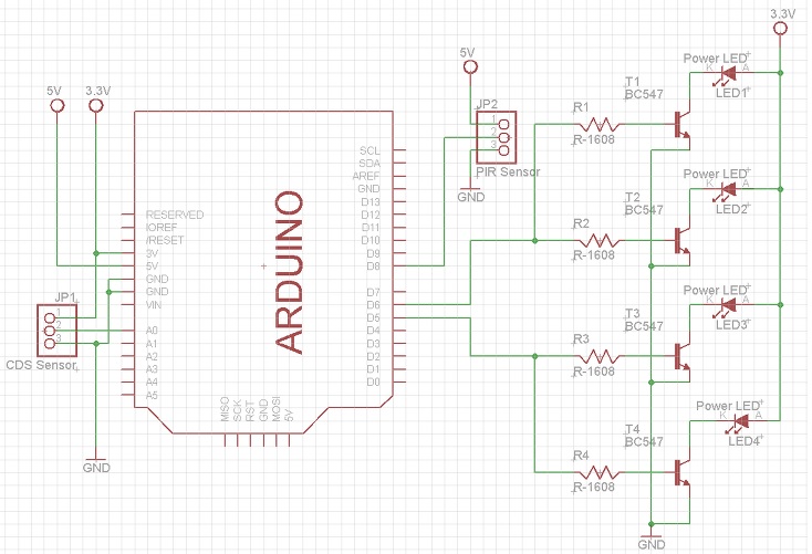
The light bulb switching circuit consists of a five-volt relay, a transistor key and a pair of discrete components:

GPIO 13 was used as the Arduino control output (initialization line: pinMode (13, OUTPUT);)
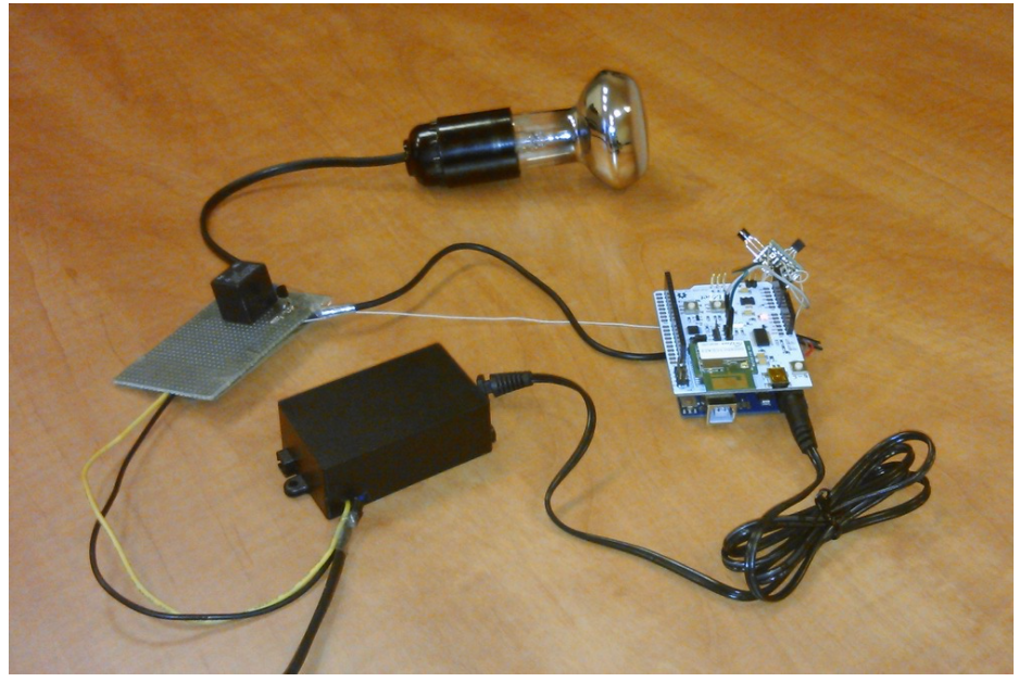
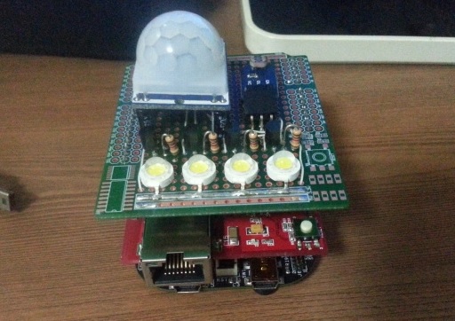
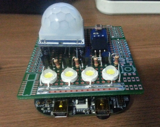
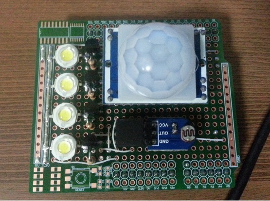
In general, the layout turned out like this:

In a black box – a ~ 220V power supply – > = 9V.
To quickly test the control of a light bulb from a tablet or smartphone under Android, you can use ready-made programs that can send TCP / UDP packets, for example, UDP Sender or TCP / UDP Server. Likewise for iOS.
In general, testing has shown that even with the use of the simplest algorithms, it is possible to achieve stable operation of the system.
Other options are to use the capabilities of the built-in WEB-server of the module for GPIO control (5 pcs.) And the ability to customize the firmware of the module by the manufacturer. Both options are interesting in that they allow you to do without an external controller / processor. But that is another story.
* A small video – in the comments.
COMMENTS