components
Hardware Components
Manuel Iglesias
X 1
Project Description
About.
The W5100S-EVB-Pico board from Wiznet is an Ethernet ready compatible Rapsberry Pi Pico board. The board uses W5100S IC from Wiznet to provide Ethernet and RP2040 microcontroller from Raspberry Pi. Is a nice compact board that can be used for many project, it can run be programmed in micropython and arduino for easy development, or using the C SDK for full control.
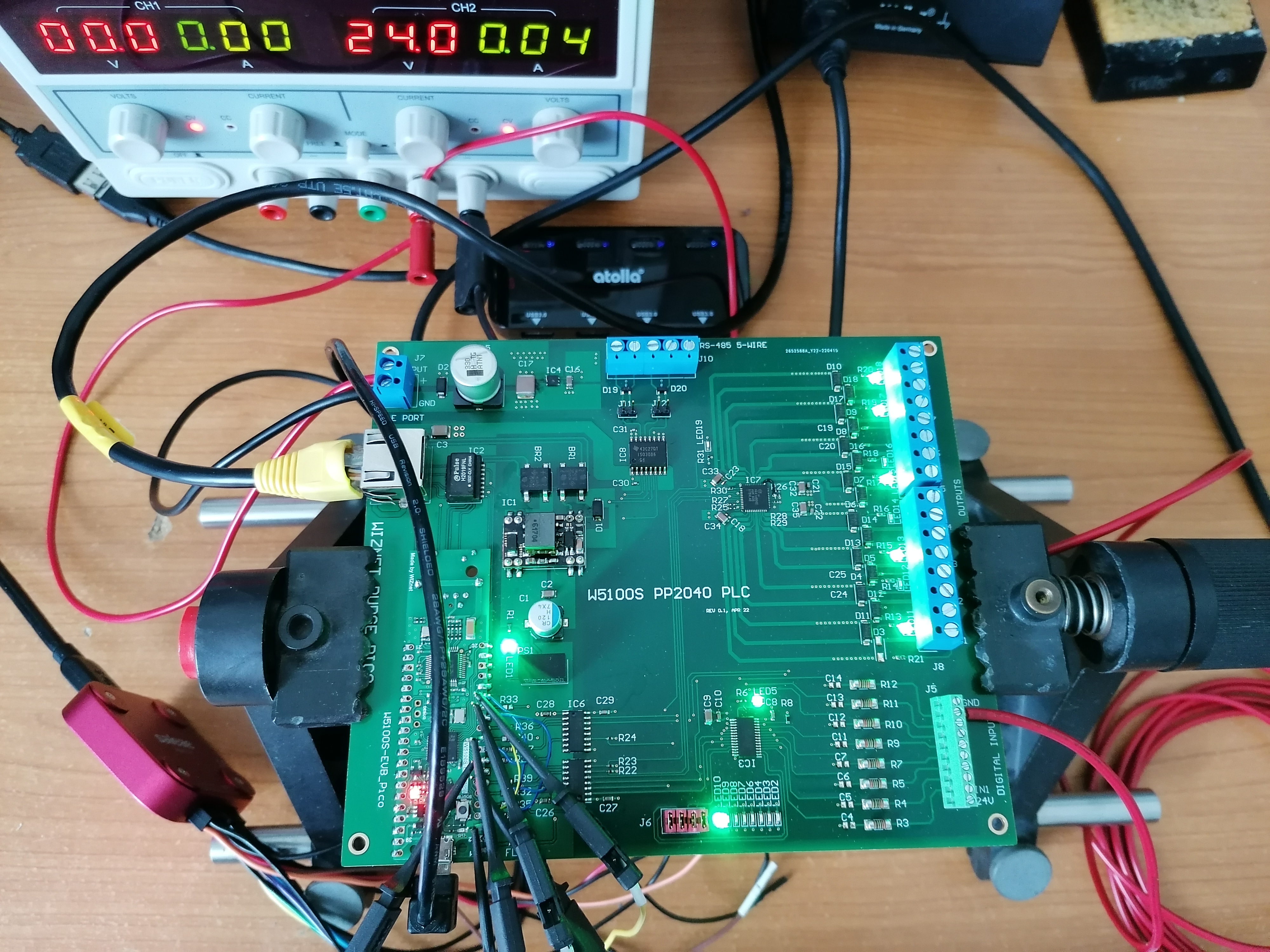
I decided to create a Industrial board capable of doing Digital Inputs and Outputs and well as communications over RS-485. In addition I have added Power Over Ethernet hardware and fully isolation of MCU from field I/O.
To demonstrate the hardware functionality I have created an Arduino code based on some example from OpenPLC project with a very simple Ladder logic diagram that exercise the I/O of the board.
Printed Circuit Board Design.
The PCB is a 6.2 in. by 5.5 in. 4 layer board. It is probably not easy to solder by hand unless you have a reflow oven, a stencil and solder paste at hand, specially because of a couple of IC that are QFN.

Wiznet EVB module.
The W5100S-EVB-Pico module footprint was easily taken from Wiznet design files, thou the pinout is the same as the raspberry pi pico board, the footprint on board also has the Ethernet pins for soldering the module including the RJ-45 lines after this is removed carefully. It is probably a task that you need to tackle with a lot of patient and lot of Flux and soldering wick.

Power Over Ethernet.
The magnetics that comes with the Wiznet EVB is an integrated magnetic RJ-45 Jack from Wiznet as well. In order to provide PoE an external PoE magnetics is used as well as a module. The magnetic is Pulse P/N H2019FNL and PoE module is Silvertel Ag9903M. This version of the module was the only I have available, it provides 3.3V output. There is a 5V output which should be the preferred choice in order to feed the module though the Vsys pin. To solve the issue on this revision of the board, I decide to use a DC-DC converter module. One module I found capable of doing the conversion is also isolated but provides unregulated output, so the voltage can be slightly higher than 5V. The part number is 1S4E_0305S1U. I would say the design works but it is not optimal since the rail voltage is 5.5V, so others IC will be operating at max voltage. As I am using a diode to feed thru the Vsys pin, with 5.5V, we can have both the USB cable connected and the PoE Ethernet cable at the same time, in this case the PoE will supply the voltage to the Wiznet EVB module.

In order to be fully industrial additional protection (in the form of TVS diodes) should be included, but I will left that to reader or a next revision.
Isolation.
The isolation is done by using digital isolators on the I/O lines from the microcontrollers to the Industrial Digital I/O chips. For I/O isolation two MAX14850 IC are used, for isolated RS-485 an ISO3086DW is used.
Industrial I/O.
The Digital Outputs are simplified by using MAX14900 IC, it allows to use up to 36V outputs in push-pull or high side configuration.The outputs are controlled using SPI bus. There are different modes but essentially I am using 16 bit transactions as I can do it easily with the RP2040. The 16 bit transaction allow me send the 8-bit output value followed by the 8-bit output configuration in a single command. There are few additional I/O to setup this, some are already hardwired in the hardware such as the serial or parallel mode, for example since we want to use only SPI, the SRIAL input is tied to logic 5V. Close to the outputs terminal block there are LEDs for showing the current state of the output.

The digital Inputs on the other hand are simplified by using MAX31912 IC, which allow as well industrial 24V and higher signals to be detected. The chip can be energized by 24V or 5V. If using the 5V we need to make sure the 24V input is disconnected. There is an on-board regulator on the field 24V supply to get a 5V from it, but essentially the board can be simplified by not populating this regulator (or removing in a next revision) and using the built-in regulator of MAX31912. There is one caveat and it is the current consumption when using the RS-485 interface ISO3086DW IC which will probably exceed the 50 mA limit of the MAX31912 regulator.

The digital inputs don't have much configuration as the outputs, but there is a few bits to get status, such as UnderVoltage and Temperature. For simplicity I am just querying the input values in a 8-bit SPI command read.
I connected a logic analizer to the SPI1 signals on the MCU side and capture the commands when querying both devices one after the other as shown below.

The Fault LED of the MAX31912 is On in the above picture since I am supplying the IC thru the 5V regulator output in this case. Maybe next revision I should have the option to disconnect the FAULT LED indicator for this use case.
RS-485.
The Industrial RS-485 serial bus is fully isolated as well and provides 5-wires in case full duplex is needed. This revision of the board requires to do external wiring in case a 3-wire bus (half-duplex) is used and provided as well the 120 Ohm termination resistor. There is some TVS protection as shown below using D19 and D20.

Field supply.
The 24V field supply is used to energize the digital I/O, a regulator P/N MAX5084 is used to get 5V from it, it can provide up to 200mA current for comms.

Firmware.
The firmware for testing the PCB is simple enough but very ilustrative of the possibilities. It is obvious you can write custom code using the C-SDK but the idea here is not to present a final product but more integrate the hardware with some upper lavel PLC system. For that I choose to use OpenPLC project and setup the device as a slave device. I took the code from the esp32 slave device and modify for the pico. For that I use Arduino IDE. I have a git with the code, so I will highlight here the important section.
Slave loop.
The slave runs in a loop listening for connections, once a client is connected it keeps in a loop listening for incoming messages. While is in that loop, the slave read and write digital_inputs and coils respectively from the digital I/O ICs.

As you can see the updateIO function is called before and after the call to process the modbus messages. The Ethernet server is in fact listening for Modbus TCP messages on the normal port 502. In our implementation, the updateIO function only implements the read and write to the digitals I/O chips.
The following capture shoes the timing of the SPI readouts. 
OpenPLC Test Software.
I won't go into the details of how to install openPLC, all I would say is that I am using ubuntu to run openPLC as shown below.

From here it is interesting to see how the server attempts to communicate with an already configured slave at start-up. As shown, the Rudge Pico PLC slave is at 192.168.1.30.
In order to get here you need to add the configuration on the web portal. I was lazy to create a custom configuration to remove the analog I/O (input registers and holding registers) so I borrow the esp8266 one.

As you can see there is an addressing for coils starting at %QX100.0 and for discrete inputs starting at %IX100.0, the same can be seen in the console output, but in this case the address comes from the assignment in the PLC ladder program (more in a moment).
Example Ladder program.
The ladder program is created using a tool called openPLC editor, you have to install it. I have basically wired outputs to power rails with some alternating in logic (negate). To test the inputs I have connected IN7 to O7.

If you load and run the program, the openPLC software will update the slave device outputs every 100ms
 The SPI1 trace also shows more exact time when the SPI1 burst get executed after receiving the modbus TCP/IP messages.
In the following short video I show the steps to run the openPLC demo. First with all the hardware disconnected we can see in the ubuntu terminal that the openplc is attempting to connect to the pico plc. After the 24V supply and Ethernet connector is plugged in the slave device starts. There is an extra step for the system to fully start, under Arduino IDE, while initializing I wait until the serial port is open to continue execution (34s in the vid), thereafter the code enters the main loop and the slave device communicates. The outputs LED are commanded. Later in the video I show the Input IN7 changing the Output O7 on the slave. The command comes from the ladder program running in openPLC software. It can be seen on the PCB led as well as on the ooenPLC monitoring page.
Finally the Rudge Pico mounted on a DIN rail.

To Do.
The Wiznet Rudge PLC still have more functionalty to explore such as the RS-485. One possibility is to use openPLC to read a modbus RTU device using the Wiznet Rudge in the middle as a TCP to RTU bridge.
Conclusion.
Wiznet and Pico have shown to be a magic formula to build this project that offers PoE and Industrial I/O capabilities. More options and communications protocols can be added on the Network side besides the Modbus TCP. The heavy lifting of creating the hardware is already done.
Desoldering an RJ-45 is not going to work for mass production but since W5100S-Pico-EVB design files are available , it should not be difficult to include the components on the Rudge Pico board in a next revision.
Here is a link of a more readiable version of the project.
documents
Code
Slave Firmware 
openPLC Arduino Firmware for Pico
Schematics
Hardware design
Design Files
Arduino Ethernet Library
Hi mhanuel,
I’m Ron from WIZnet HK. Could I post your article to our WIZnet HK instagram account?
BTW, do you have a instagram account that I could tag you?
Best Regards,
Ron