components
Hardware Components
W5100S-EVB-Pico
X 4
WIZnet Ethernet HAT
X 4
Raspberry Pi Pico Documentation
Raspberry Pi Pico SDK Pi Pico Documentation
Pi Pico C++ SDK
Documentation and Firmware examples
Project communication Channel
Project Description
We are in an era where Edge nodes become smarter.
A need has emerged for microcontroller to interface with the outside world, provide real-time analytics and then take action.
No more data sent to cloud and the come back for simple or complicated decision. All can take place on the Edge. Where the action is. Where WIZcube is
Wizcube Ecosystem not only provides intelligence at the Edge, but has the correct interfaces to deliver the job.
WIZcube nodes can be connected with fast 10MBPS communication thanks to the W5100S chip onboard.
WIZcube Ecosystem will have an ever expanding range of modules. When needs arise, solutions can be
quickly desinged and built using the existing templates under the WIZcube umbrella and shared with the community.
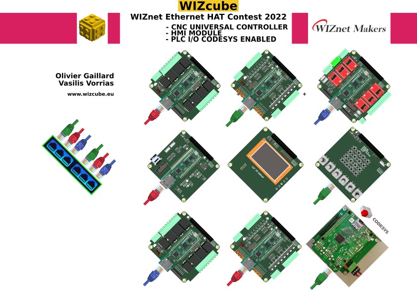
WIZcube modules are stackable and share a Raspberry Pi 40pin connector. Modules then can make a powerful 100X100x100 mm cube (height is dependent on how many board are stacked together).
WIZcube modules can work with the following configurations
1/ Raspberry PICO
2/ Raspberry PICO + WIZnet Ethernet HAT
3/ W5100S-EVB-Pico
4/ WizFi360-EVB-Pico
configurations 2, 3 and 4 supports Ethernet with hardware TCP/IP by WIZnet.
HARDWARE
The following hardware modules are designed, fabricated and tested.
M10NC02-20 PCB + BOM X1 (https://wizcube.eu/cnc.html)
M10DX01-20 PCB + BOM X1 (https://wizcube.eu/dx1.html
M10DX02-20 PCB + BOM X1 (https://wizcube.eu/dx2.html)
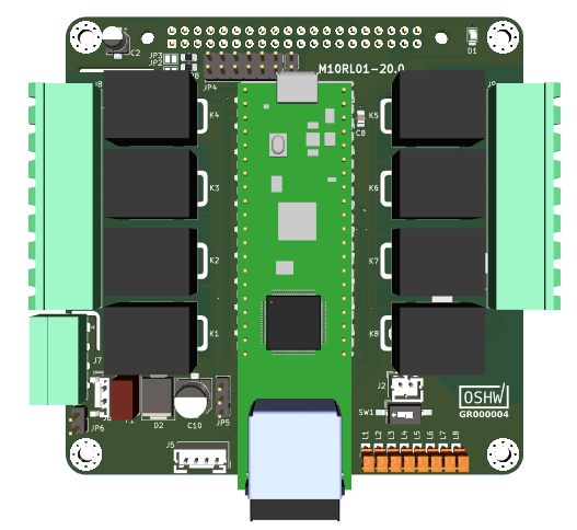
M10RL01-20 PCB + BOM X1 (https://wizcube.eu/rl1.html)
M10PS01-01 PCB + BOM X1 (https://wizcube.eu/ps1.html)*
We have tested every board with the WS5100-EVB-Pico and dedicated firmware that can be found on our GitLab.
We have also used the combination Raspberry PICO + WIZnet Ethernet HAT with absolute success.
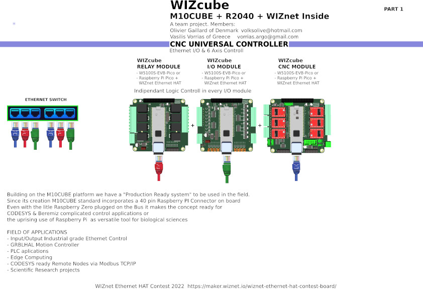
M10NC02-20 CNC Module:
This CNC module is a 6 axis CNC controller board running grblHAL code.
This board requires:
1 to 6 DRV8825 or A4988 or TMC2209 or TMC2130 or TMC5160 Stepper driver
or a small bypass module (drop in replacement of a stepstick) designed by contributor terjeiro, that can forward the stepepr control signals to external stepper motor drivers.
Work in Progress code can be found on our Github (cf. code link in the Code section below).
M10DX01-20, M10DX02-20, M10RL01-20 I/O modules:
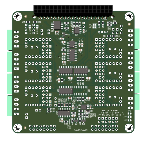
The M10DX01-20 is a +24V x8 Inputs and +24V x8 High Side Transistor Outputs board.
The M10DX02-20 is a +24V x8 Inputs and +220V SSR Outputs board.
The M10RL01-20 is a +220V x8 Outputs board.
These boards can be used for inputs reading and outputs control for Automation, Home automation, CNC control (limit switches, control signals, cooling, vaccum, etc.).
M10PS01-01 Power Supply module:
The M10PS01-01 is a Power Supply module for powering the WIZnet module stack.
A Raspberry Pi mini computer board (any model) can be connected to this board for running control software f.ex:
- CODESYS for Automation
- NODE-RED for Home Automation
- Octoprint or UGS (Universal G-code Sender) for CNC control.
It is an old design. It was not designed for the contest but it is a perfect companion for all WIZcube modules.
Raspberry Pi board when connected with this module never complains about power shortage (the known lightening bolt symbol).
The M10PS01-01 is a part of a WIZcube modular ecosystem and part of the stacked module cube.
A new version is being designed with lots of new functionalities and bare chip RP2040 Raspberry Pico on board.
The following modules are being designed and prototyped:
M10HM01-19 PCB + BOM X1 (HMI DISPLAY MODULE: https://wizcube.eu/hm1.html)
M10HM02-19 PCB + BOM X1
M10HMI was designed primarily for CNC Remote Control (MPG) but can be used as a general purpose HMI. It can be installed in any room for Home automation control f.ex.
Due to short time and shortage of components, we did not have the M10HM01-19 PCB ready on time (final version will be codename M10HM01-20).
As a substitute, we did a hand wired Prototype to proof the concept.
The M10HM01-19 prototype runs a test program transferring rotary encoder and keypad data to M10DX01-20 via Modbus TCP, the firmware can be found on our GitLab.
A bit of project history and project development:
WIZcube idea was born of the slogan “M10CUBE + RP2040 + WIZnet Ethernet HAT Inside”.
That is Ethernet out of the box for our M10CUBE modules. Every M10CUBE we had designed and the ones we are going
in the future will be “Ethernet enabled” (WiFi..) because of the WIZnet Ethernet HAT addition. Only small modifications
were needed to share the same pins for the SPI communication.
Here is links to the initial M10Cube project and where the CNC board idea sprouted:
https://gitlab.com/m10cube/m10
https://hackaday.io/project/171770-m10cube
https://github.com/grblHAL/RP2040/discussions/18
That is also where the 2 developers of this project met for the first time and where their discussion and ideas started to collide. We have since then worked from 2 different places, one in Greece and one in Denmark without having ever physically met each other but still we made it work and here is the result of that hard work !
Next steps:
A need has emerged for microcontroller to interface with the outside world, provide real-time analytics and then take action.
No more data sent to cloud and the come back for simple or complicated decision. All can take place on the Edge. Where the action is. Where WIZcube is
Wizcube Ecosystem not only provides intelligence at the Edge, but has the correct interfaces to deliver the job.
WIZcube nodes can be connected with fast 10MBPS communication thanks to the W5100S chip onboard.
WIZcube Ecosystem will have an ever expanding range of modules. When needs arise, solutions can be
quickly desinged and built using the existing templates under the WIZcube umbrella and shared with the community.
WIZcube modules are stackable and share a Raspberry Pi 40pin connector. Modules then can make a powerful 100X100x100 mm cube (height is dependent on how many board are stacked together).
WIZcube modules can work with the following configurations
1/ Raspberry PICO
2/ Raspberry PICO + WIZnet Ethernet HAT
3/ W5100S-EVB-Pico
4/ WizFi360-EVB-Pico
configurations 2, 3 and 4 supports Ethernet with hardware TCP/IP by WIZnet.
HARDWARE
The following hardware modules are designed, fabricated and tested.
M10NC02-20 PCB + BOM X1 (https://wizcube.eu/cnc.html)
M10DX01-20 PCB + BOM X1 (https://wizcube.eu/dx1.html
M10DX02-20 PCB + BOM X1 (https://wizcube.eu/dx2.html)
M10RL01-20 PCB + BOM X1 (https://wizcube.eu/rl1.html)
M10PS01-01 PCB + BOM X1 (https://wizcube.eu/ps1.html)*
We have tested every board with the WS5100-EVB-Pico and dedicated firmware that can be found on our GitLab.
We have also used the combination Raspberry PICO + WIZnet Ethernet HAT with absolute success.
M10NC02-20 CNC Module:
This CNC module is a 6 axis CNC controller board running grblHAL code.
This board requires:
1 to 6 DRV8825 or A4988 or TMC2209 or TMC2130 or TMC5160 Stepper driver
or a small bypass module (drop in replacement of a stepstick) designed by contributor terjeiro, that can forward the stepepr control signals to external stepper motor drivers.
Work in Progress code can be found on our Github (cf. code link in the Code section below).
M10DX01-20, M10DX02-20, M10RL01-20 I/O modules:
The M10DX01-20 is a +24V x8 Inputs and +24V x8 High Side Transistor Outputs board.
The M10DX02-20 is a +24V x8 Inputs and +220V SSR Outputs board.
The M10RL01-20 is a +220V x8 Outputs board.
These boards can be used for inputs reading and outputs control for Automation, Home automation, CNC control (limit switches, control signals, cooling, vaccum, etc.).
M10PS01-01 Power Supply module:
The M10PS01-01 is a Power Supply module for powering the WIZnet module stack.
A Raspberry Pi mini computer board (any model) can be connected to this board for running control software f.ex:
- CODESYS for Automation
- NODE-RED for Home Automation
- Octoprint or UGS (Universal G-code Sender) for CNC control.
It is an old design. It was not designed for the contest but it is a perfect companion for all WIZcube modules.
Raspberry Pi board when connected with this module never complains about power shortage (the known lightening bolt symbol).
The M10PS01-01 is a part of a WIZcube modular ecosystem and part of the stacked module cube.
A new version is being designed with lots of new functionalities and bare chip RP2040 Raspberry Pico on board.
The following modules are being designed and prototyped:
M10HM01-19 PCB + BOM X1 (HMI DISPLAY MODULE: https://wizcube.eu/hm1.html)
M10HM02-19 PCB + BOM X1
M10HMI was designed primarily for CNC Remote Control (MPG) but can be used as a general purpose HMI. It can be installed in any room for Home automation control f.ex.
Due to short time and shortage of components, we did not have the M10HM01-19 PCB ready on time (final version will be codename M10HM01-20).
As a substitute, we did a hand wired Prototype to proof the concept.
The M10HM01-19 prototype runs a test program transferring rotary encoder and keypad data to M10DX01-20 via Modbus TCP, the firmware can be found on our GitLab.
A bit of project history and project development:
WIZcube idea was born of the slogan “M10CUBE + RP2040 + WIZnet Ethernet HAT Inside”.
That is Ethernet out of the box for our M10CUBE modules. Every M10CUBE we had designed and the ones we are going
in the future will be “Ethernet enabled” (WiFi..) because of the WIZnet Ethernet HAT addition. Only small modifications
were needed to share the same pins for the SPI communication.
Here is links to the initial M10Cube project and where the CNC board idea sprouted:
https://gitlab.com/m10cube/m10
https://hackaday.io/project/171770-m10cube
https://github.com/grblHAL/RP2040/discussions/18
That is also where the 2 developers of this project met for the first time and where their discussion and ideas started to collide. We have since then worked from 2 different places, one in Greece and one in Denmark without having ever physically met each other but still we made it work and here is the result of that hard work !
Next steps:
- Add Ethernet communication to grblHAL for the M10NC02 Module with WIZnet iolibrary_Driver.
- Add Telnet and Websocket communication to grblHAL for M10NC02.
- Add I2C or SPI communication with M10DX01/02 and M10RL01 (first step).
- Add Modbus communication with M10DX01/02 and M10RL01 (second step).
- Add input interruption configuration to M10DX01/02 to specify which input can generate an interrupt.
- Add input capture and output compare to MX10DX01/02.
- Add zero crossing detection to M10DX02.
- Finalize M10HMI01/02 design, production and testing.
- Redesign M10PS01-01.
- Redesign the cube mechanical casing.
- Continue the development of the tools to support WIZCube (Kicad template,etc.)
- Continue to document the WIZCube projet (WIZCube.eu, Gitlab, github, etc.)
- Keep on going the good ideas with the WIZnet modules.
documents
Code
M10HM01 prototype Code 
Code for the prototype M10HM01 Module using MODBUS to control the M10DX01/02
CODESYS demo Code
Demo code to run on any Raspberry Pi mini computer board that control the M10DX01/02 Module or M10RL01 Module using MODBUS
Future Dishwasher real use case Code
Work in progress of a dishwasher code using the M10DX02
Future Greenhouse real use case Code
Work in progress of a WIZCube stack for the control and regulation of a greenhouse (Temperature control/regulation, watering, shading, real time information feedback
CNC controller + I/O + HMI real use case Code
Work in progress of a CNC controller M10NC02 Module connected to a M10DX01 Module and M10HM01 Module
Future Home Automation real use case Code
Work in progress of an Home automation project using the M10DX01 Module connected to a Raspberry Pi running NODE-RED and using MQTT protocol to communicate
M10NC02 grblHAL Code
grblHAL code modified to run on M10NC02 (Work in progress)
Schematics
M10NC02-20 MODULE GERBER
V 20.0
M10DX01-20 MODULE GERBER
V 20.0
M10DX02-20 MODULE GERBER
V 20.0
M10RL01-20 MODULE GERBER
V 20.0
RELAY MODULE SCHEMATIC
V 20.0
CNC MODULE SCHEMATIC
V 20.0
INPUT OUTPUT SCHEMATIC
V 20.0
M10HM01-20
HMI MAIN MODULE
M10HM02-20
HMI LCD MODULE
INPUT OUTPUT SSR TRIAC SCHEMATIC
V 20.0
M10NC02-20 MODULE BOM
V 20.0
M10DX01-20 MODULE BOM
V 20.0
M10DX02-20 MODULE BOM
V 20.0
M10RL01-20 MODULE BOM
V 20.0
Others
WIZcube video
youtube
GitLab
All about the project
Hackaday
Log files about the project in Hackaday.io
WIZcube interview
Dr Dalmaris interviewing Vasilis Vorrias
CNC PRESENTATION
wizcube.eu WEB PAGE
I/O TRANSISTOR PRESENTATION
wizcube.eu WEB PAGE
I/O TRIAC PRESENTATION
wizcube.eu WEB PAGE
RELAY PRESENTATION
wizcube.eu WEB PAGE
HMI PRESENTATION
wizcube.eu WEB PAGE
cover

cover page svg format
page 1
page 1 svg format
page 2

page 2 svg format
page 3

page 3 svg format
wiznet conest idea
wiznet conest idea corrected
CNC MODULE PCB TOP

3D IMAGE TOP
INPUT OUTPUT PCB TOP

3D IMAGE TOP
INPUT OUTPUT SSR PCB TOP

3D IMAGE TOP
RELAY PCB TOP
3D IMAGE TOP
CNC MODULE PCB BOTTOM
3D IMAGE BOTTOM
Arduino Ethernet Library
Hi WIZnet team. We have submitted our idea but we did not receive any confirmation email. How do we know that the submission was correct and on time? Thank you
Hi, idea submission stage is until Feb 22 and final project can be submitted till April 30. Feel free to update your project anytime until April 30!
Thanks for the answer but my question is how can we be sure that we make the submission correctly on time. We are wondering If only make a draft submission and not permanent one. Sorry for the trouble
I just checked, your idea was submitted successfully. We will check about email delivery. Should you have any other questions, do not hesitate to contact us contest@wiznet.io.
Hi WIZnet team. Some time ago we uploaded schematics in PDF. Yesterday we uploaded our new corrected schematics Ver. 20.0 but we can see no way to delete the old obsolete schematics. Please inform us how to do it. Thank you.
Hi, thanks for information. We will fix this.
Thank you it is working now. Job done
EBMC ! ATK !!
Hi wiznet support team. I just uploaded 5 images of the populated modules but I can not see the images in our project.
Actually I did it twice. Is any limit of the number of he uploaded images? These are real populated modules.
Thanks
Hi wiznet support team. We still can not upload images to our account. We uploaded many times and images not shown.
Please give us a direct email or telephone to communicate Thanks
Sorry for the inconvenience. Please try again it or send us contest@wiznet.io.
Hi Vorrias,
I’m Ron from WIZnet HK. Could I post your article to our WIZnet HK instagram account?
BTW, do you have a instagram account that I could tag you?
Best Regards,
Ron