
components
Hardware Components
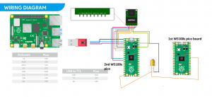
W5100s-EVB-pico
X 2
Used one for controlling dispenser motors, sending notification to MQTT using Ethernet and second pico board is used for peron detection using tinyML application
Servo Motor
X 1
To control the medicine dispencer
Motor driver
X 1
To control 2 DC motors
Potentiometer
X 1
Raspberry Pi OS
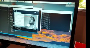
processing To run raspberry pi as well as code the second pico board
To view the person detection output in a window
To view the MQTT messages by connecting to the broker
To install the MQTT broker
Project Description
The description of the project is as follows:

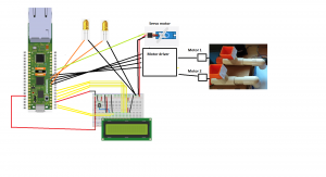
The working of the first pico board is as follows: The 1st W5100s pico baord is program in such a way that it displays the digital clock in the LCD screen for 12 hour format and functions as the clock progresses. When the code is loaded into the W5100s pico board, the time is set to 10:54:00 AM in Hour, Minute and second format. When the time is 11.00 AM in the board The fish food is dispensed using the 1st motor. When the first motor starts dispensing LCD displays "Fish Feeding " status and 1st LED is ON. When its completed in 5 secs LCD displays "Fish Completed", and 1st LED turns OFF and the notification is sent to the MQTT server in the "fish" topic. When the Time is 11:01 AM in the W5100s pico board display, 2nd Motor turns on with the second LED and the dog food is dispensed with LCD display "Dog Feeding". After 15 secs when the dig food is dispensed motor is stopped, 2nd LED is turned OFF, LCD displays "dog completed". AFter this MQTT messages is sent as DOG completed under the topic "dog" . At 11.15 AM servo motor is turned to dispense medicine. After the medicine is dispensed the 1st pico board waits for the 2nd W5100s pico board to send a notification using a gpio HIGH logic. GPIO26 anolog A0 is made to read anlog inputs, when the values is read high a MQTT message is sent to the server under the topic "person" with the message person detected. Once everything is completed MQTT message is sent to the server notifying all tasks are completed in that time.


Once the person is detected LED will Turn ON and a analog signal is received in the 1st W5100s pico board. MQTT message from the 1st W5100s pico board is sent to server notifying "person detected".
Raspberry pi server is also running a server to store the mqtt messages as a db file. db files store all the messages in a table with the following structure.
SLNo , Topic, Message , Time created
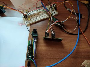
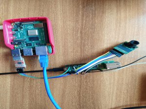
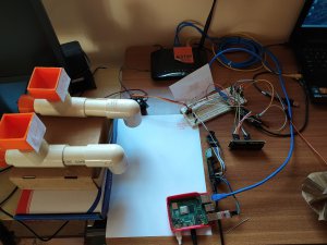
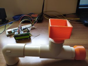
Overall Setup of the project:
Additional information's
3d models were printed in the 3d printer to dispense the foods for the pets. 3 different things were printed. Archimedes screw, top box and a holder for the Archimedes screw. 2 sets were created. All the components printed are here:
Archimedes screw:

Holder for Archimedes screw:
Top Box:
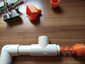
the designs of the completed product is shown below:
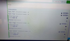
MQTT lens is used to view the message in the system with the subscribed topics. 5 topics are subscribed and connected to the Mqtt server (raspberry pi).

Viewed messages in the MQTT lens:

- Explain the 1st W5100s pico board code and working
- Explain the second w5100s pico board code and working
- Explain about the raspberry pi board
- Explain all the output.
- 1st W5100s pico board code:
The working of the first pico board is as follows: The 1st W5100s pico baord is program in such a way that it displays the digital clock in the LCD screen for 12 hour format and functions as the clock progresses. When the code is loaded into the W5100s pico board, the time is set to 10:54:00 AM in Hour, Minute and second format. When the time is 11.00 AM in the board The fish food is dispensed using the 1st motor. When the first motor starts dispensing LCD displays "Fish Feeding " status and 1st LED is ON. When its completed in 5 secs LCD displays "Fish Completed", and 1st LED turns OFF and the notification is sent to the MQTT server in the "fish" topic. When the Time is 11:01 AM in the W5100s pico board display, 2nd Motor turns on with the second LED and the dog food is dispensed with LCD display "Dog Feeding". After 15 secs when the dig food is dispensed motor is stopped, 2nd LED is turned OFF, LCD displays "dog completed". AFter this MQTT messages is sent as DOG completed under the topic "dog" . At 11.15 AM servo motor is turned to dispense medicine. After the medicine is dispensed the 1st pico board waits for the 2nd W5100s pico board to send a notification using a gpio HIGH logic. GPIO26 anolog A0 is made to read anlog inputs, when the values is read high a MQTT message is sent to the server under the topic "person" with the message person detected. Once everything is completed MQTT message is sent to the server notifying all tasks are completed in that time.
- 2nd W5100s pico board:
- Create a directory called pico
- Install required dependencies
- Download the pico-sdk, pico-examples, pico-extras, and pico-playground repositories
- Define PICO_SDK_PATH, PICO_EXAMPLES_PATH, PICO_EXTRAS_PATH, and PICO_PLAYGROUND_PATH in your ~/.bashrc
- Build the blink and hello_world examples in pico-examples/build/blink and pico-examples/build/hello_world
- Download and build picotool (see Appendix B). Copy it to /usr/local/bin. • Download and build picoprobe (see Appendix A).
- Download and compile OpenOCD (for debug support)
- Download and install Visual Studio Code
- Install the required Visual Studio Code extensions (see Chapter 6 for more details)
- Configure the Raspberry Pi UART for use with Raspberry Pi Pico
- raspberry pi setup and results:
Once the person is detected LED will Turn ON and a analog signal is received in the 1st W5100s pico board. MQTT message from the 1st W5100s pico board is sent to server notifying "person detected".
Raspberry pi server is also running a server to store the mqtt messages as a db file. db files store all the messages in a table with the following structure.
SLNo , Topic, Message , Time created
Overall Setup of the project:
Additional information's
3d models were printed in the 3d printer to dispense the foods for the pets. 3 different things were printed. Archimedes screw, top box and a holder for the Archimedes screw. 2 sets were created. All the components printed are here:
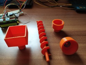
Archimedes screw:

Holder for Archimedes screw:

Top Box:

the designs of the completed product is shown below:
MQTT lens is used to view the message in the system with the subscribed topics. 5 topics are subscribed and connected to the Mqtt server (raspberry pi).
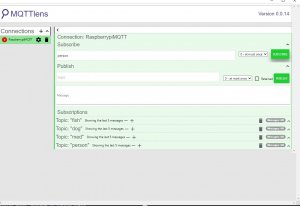
Viewed messages in the MQTT lens:
documents
Code
1st pico board 
Is coded using arduino IDE for controlling Fish, Dog food dispenser motor and sending the notification after completing to the MQTT server built on raspberry pi
Paho MQTT server
File to store and save MQTT messages indb file using sqlite
base html
base html file to view the mQTT messages in the server its in he directory /pahomqtt/templates
index html
Index html to view the mQTT messages in the server its in he directory /pahomqtt/templates
Person detection PDE
This is runned in the processing software in the Raspberry pi for viewing the persons images and detection percentage
TinyML person detection edited code
This file is one of the file present for tiny ML person detection . modified it to turn LED ON and OFF id the person detection probability is more than 75%
Mbed Ethernet Library
Was not able to add upload a working video
Will upload in YouTube and add the link for the working video in the comment below
https://youtu.be/STnhz3VQg-c
Hi harsha,
I’m Ron from WIZnet HK. Could I post your article to our WIZnet HK instagram account?
BTW, do you have a instagram account that I could tag you?
Best Regards,
Ron